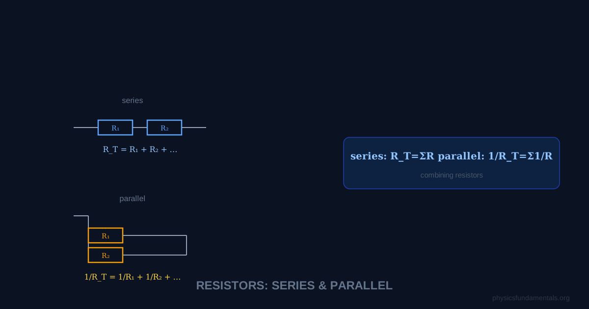
For resistors in series, the total resistance is R_total = R₁ + R₂ + R₃ — resistances simply add. For resistors in parallel, the reciprocals add: 1/R_total = 1/R₁ + 1/R₂ + 1/R₃, giving a total resistance that is always less than the smallest individual resistor. These two rules, combined with Ohm's law (V = IR) and Kirchhoff's laws, let you analyse any resistor network.
Getting these rules backwards is one of the most common mistakes in circuit problems. The key to remembering them: series resistors have nowhere else for current to go, so all resistance stacks up. Parallel resistors give current multiple paths, so the total resistance decreases — more paths means less total opposition.
- Series rule: R_total = R₁ + R₂ — same current, voltages add
- Parallel rule: 1/R_total = 1/R₁ + 1/R₂ — same voltage, currents add
- Product-over-sum shortcut for two parallel resistors
- 5 worked examples including mixed series-parallel networks
- How to identify which resistors are in series vs parallel
Resistors in Series
Resistors are in series when connected end-to-end in a single path — the same current flows through each one.
Key facts for series circuits:
- Current: identical through every resistor — I₁ = I₂ = I₃ = I
- Voltage: splits across resistors in proportion to resistance — V₁ = IR₁, V₂ = IR₂
- Total voltage: V_total = V₁ + V₂ + V₃ (voltages add)
- Total resistance: always greater than the largest individual resistor
Resistors in Parallel
Resistors are in parallel when connected between the same two nodes — the same voltage appears across each one.
Key facts for parallel circuits:
- Voltage: identical across every branch — V₁ = V₂ = V₃ = V
- Current: splits between branches — I₁ = V/R₁, I₂ = V/R₂
- Total current: I_total = I₁ + I₂ + I₃ (currents add)
- Total resistance: always less than the smallest individual resistor
Product-over-sum shortcut (two resistors only)
This shortcut only works for exactly two resistors. For three or more, use the reciprocal formula.
Equal resistors in parallel
If n identical resistors of value R are in parallel:
Three 30 Ω resistors in parallel → R_total = 30/3 = 10 Ω.
5 Worked Examples
Example 1 — Pure series
Problem: Three resistors of 10 Ω, 22 Ω, and 47 Ω are connected in series to a 12 V supply. Find: (a) total resistance, (b) current, (c) voltage across the 22 Ω resistor.
Solution:
(a) R_total = 10 + 22 + 47 = 79 Ω
(b) I = V/R = 12/79 = 0.152 A
(c) V₂₂ = IR = 0.152 × 22 = 3.34 V
Example 2 — Pure parallel
Problem: A 6 Ω and a 12 Ω resistor are in parallel. What is the equivalent resistance?
Solution:
R = (6 × 12)/(6 + 12) = 72/18 = 4 Ω
Note: 4 Ω is less than the smallest resistor (6 Ω) ✓
Example 3 — Three in parallel
Problem: Resistors of 4 Ω, 6 Ω, and 12 Ω are in parallel. Find R_total.
Solution:
1/R = 1/4 + 1/6 + 1/12 = 3/12 + 2/12 + 1/12 = 6/12 = 1/2
R_total = 2 Ω
Example 4 — Series-parallel combination
Problem: R₁ = 5 Ω is in series with a parallel combination of R₂ = 6 Ω and R₃ = 12 Ω. The supply is 9 V. Find the total current drawn from the supply.
Solution:
Step 1 — Parallel equivalent: R₂₃ = (6 × 12)/(6 + 12) = 4 Ω
Step 2 — Total resistance: R_total = R₁ + R₂₃ = 5 + 4 = 9 Ω
Step 3 — Total current: I = V/R = 9/9 = 1 A
Example 5 — Finding an unknown resistance
Problem: Two resistors are in parallel. The total resistance is 4 Ω. One resistor is 12 Ω. Find the other.
Solution:
1/R_total = 1/R₁ + 1/R₂
1/4 = 1/12 + 1/R₂
1/R₂ = 1/4 − 1/12 = 3/12 − 1/12 = 2/12 = 1/6
R₂ = 6 Ω
How to Identify Series vs Parallel
This is where most students struggle in complex circuits. Use these tests:
- Series test: If removing one component breaks the only path for current, those components are in series.
- Parallel test: If two components share exactly the same two nodes (junctions) at both ends, they are in parallel.
- Redraw the circuit: Complex-looking circuits often simplify dramatically when redrawn clearly. Identify nodes first, then trace paths between them.
Real-World Applications
Christmas lights: Old-style lights were in series — one failure killed the whole string. Modern LED lights use parallel wiring so one failure doesn't affect the others.
Household wiring: All appliances in a house are wired in parallel across the mains supply. Each appliance gets the full mains voltage (230 V in the UK), and each draws its own current independently.
Voltage dividers: Two resistors in series form a voltage divider — a circuit that produces a fraction of the supply voltage. Used extensively in electronics for biasing transistors and sensor circuits.
Deriving the Combination Rules from First Principles
Series (same current, voltages add): From KVL: V_total = V₁ + V₂ + V₃. Since I is the same through each: IR_total = IR₁ + IR₂ + IR₃ → R_total = R₁ + R₂ + R₃.
Parallel (same voltage, currents add): From KCL: I_total = I₁ + I₂ + I₃. Since V is the same across each: V/R_total = V/R₁ + V/R₂ + V/R₃ → 1/R_total = 1/R₁ + 1/R₂ + 1/R₃.
For exactly two resistors in parallel, a shortcut avoids fractions:
Current and Voltage Distribution
Voltage divider (series): The voltage across each resistor in a series chain is proportional to its resistance:
Current divider (parallel — for two resistors): The current through each parallel branch is inversely proportional to its resistance:
Note: the current divider formula puts the OTHER resistor in the numerator — the smaller resistor carries the larger current.
Worked Example 5 — Mixed series-parallel network
Problem: A 12 V battery connects to: R₁ = 6 Ω in series with a parallel combination of R₂ = 8 Ω and R₃ = 24 Ω. Find: (a) equivalent resistance, (b) total current, (c) voltage across R₁, (d) current through R₂ and R₃.
Solution:
(a) R₂₃ = 8 × 24/(8+24) = 192/32 = 6 Ω; R_total = 6 + 6 = 12 Ω
(b) I_total = V/R_total = 12/12 = 1 A
(c) V_R₁ = I × R₁ = 1 × 6 = 6 V
(d) V_R₂₃ = 12 − 6 = 6 V; I_R₂ = 6/8 = 0.75 A; I_R₃ = 6/24 = 0.25 A
Check: 0.75 + 0.25 = 1 A ✓
Worked Example 6 — Finding unknown resistance
Problem: Two resistors in parallel give 4 Ω combined. One resistor is 12 Ω. Find the other.
Solution:
1/R_total = 1/R₁ + 1/R₂ → 1/4 = 1/12 + 1/R₂
1/R₂ = 1/4 − 1/12 = 3/12 − 1/12 = 2/12 = 1/6
R₂ = 6 Ω
Check: 12×6/(12+6) = 72/18 = 4 Ω ✓
Resistors in Practical Circuits
Understanding series and parallel combinations is essential for practical circuit design:
- LED driving: LEDs require a specific current (typically 10–20 mA) and a specific voltage (~2–3 V depending on colour). A series resistor limits the current: R = (V_supply − V_LED)/I_LED. Multiple LEDs in series share the same current; in parallel they each need their own series resistor (or current deviations cause uneven brightness).
- Potential dividers for sensors: a fixed resistor in series with a variable sensor (thermistor, LDR) creates a voltage that changes with the physical quantity being sensed. Output voltage: V_out = V_supply × R_fixed/(R_fixed + R_sensor).
- Battery banks: cells in series add voltage; cells in parallel add current capacity (charge). A 12 V car battery consists of six 2 V lead-acid cells in series. A phone with two battery cells in parallel provides double the capacity at the same voltage.
Power in Series and Parallel Combinations
In a series circuit, the resistor with the largest resistance dissipates the most power (P = I²R, same I). This is why the highest-resistance component in a series chain gets hottest and fails first — a design consideration in all series-connected loads.
In a parallel circuit, the resistor with the smallest resistance dissipates the most power (P = V²/R, same V, smallest R gives highest P). House ring mains and lighting circuits are parallel — each appliance gets the full 230 V regardless of other appliances, and draws current according to its own resistance (wattage rating).
Total power: in either series or parallel, total power P_total = V_total × I_total = V_total²/R_total = I_total² × R_total. Or equivalently: P_total = P₁ + P₂ + P₃ — power is always additive, regardless of the circuit topology.
Resistor Tolerance and Preferred Values
Commercial resistors come in standard values (E12, E24, E96 series) with tolerance ratings of ±10%, ±5%, ±1%. The E12 series has 12 values per decade: 1.0, 1.2, 1.5, 1.8, 2.2, 2.7, 3.3, 3.9, 4.7, 5.6, 6.8, 8.2 — spaced so that the maximum tolerance range of one value just overlaps the minimum of the next. When designing circuits, resistors must often be combined to achieve a value not in the standard series. Combining a 6.8 kΩ and 1.2 kΩ in series gives 8.0 kΩ; combining two 10 kΩ in parallel gives 5.0 kΩ — both achievable from E12 components to ±10% tolerance.
Exam Strategy for Complex Resistance Networks
For any multi-resistor network: (1) identify all series and parallel groups, working from the innermost combination outward; (2) reduce step by step — replace each group with its equivalent; (3) find total current from V/R_total; (4) work back through the original circuit, finding voltages and currents at each stage using Ohm's law. The key skill is correctly identifying which resistors share the same current (series) and which share the same voltage (parallel). If a resistor has both ends connected to the same pair of nodes as another resistor, they are in parallel. If the only path for current through one resistor also passes through another, they are in series. Drawing the circuit and tracing current paths before writing equations prevents most identification errors.
Common pitfall: assuming all resistors in a circuit are either all in series or all in parallel. Real circuits are almost always mixed — some resistors in series within a parallel branch, or parallel groups in series with other resistors. Reduce systematically and never try to sum all resistances in a mixed circuit without first identifying the topology correctly.
Summary of Key Rules
Series: R_total = R₁ + R₂ + ... (resistance adds); same current through all; voltages add. Parallel: 1/R_total = 1/R₁ + 1/R₂ + ... (reciprocals add); same voltage across all; currents add. For two parallel resistors: R = R₁R₂/(R₁+R₂). Adding a resistor in series always increases total resistance. Adding a resistor in parallel always decreases total resistance (below the smallest individual value). Power is always additive: P_total = ΣPᵢ regardless of topology. These rules, combined with Ohm's law V = IR, are sufficient to analyse any purely resistive DC circuit.
The series and parallel combination rules are the most-used tools in all of circuit analysis — they appear in every circuit problem at A-Level and remain central through undergraduate electronics. Beyond simple DC circuits, the same rules extend to AC with impedances: capacitors in series: 1/C_total = 1/C₁ + 1/C₂ (reciprocals, like parallel resistors); capacitors in parallel: C_total = C₁ + C₂ (like series resistors). The seeming reversal happens because capacitance is proportional to the area available for charge storage — parallel capacitors present more area. Understanding why the rules work (from KVL and KCL), not just memorising them, allows you to apply them correctly in any configuration and to recognise and analyse the ladder networks, bridge circuits, and filter networks that build on these fundamentals.
Worked Example 7 — Ladder network simplification
Problem: Find the total resistance between terminals A and B of this network: from A, 10 Ω goes right to node C; from C, 20 Ω goes down to B; also from C, another 10 Ω goes right to node D; from D, 20 Ω goes down to B. (Two identical T-sections in series.)
Solution:
Right section (C-D-B): 10 Ω in series with 20 Ω parallel to nothing (D connects only to B via 20 Ω at the end) → R_right = 10 + 20 = 30 Ω
At node C: 20 Ω (C to B) in parallel with 30 Ω (C through D to B): R_C = 20×30/(20+30) = 600/50 = 12 Ω
Total from A: 10 Ω (A to C) + 12 Ω (C to B) = 22 Ω
This ladder simplification technique — working from the far end back toward the source — is the standard method for all ladder and attenuator networks.
The fundamental reason series resistance adds and parallel conductance adds (1/R_parallel rule) comes from the physical nature of each topology. In series, resistors are like friction on consecutive stretches of road — each adds independent opposition to the same flow. In parallel, resistors offer independent paths for the flow — more paths means less total opposition. Conductance G = 1/R (unit: siemens, S) is often more natural for parallel circuits: G_parallel = G₁ + G₂ + G₃ (conductances add in parallel). Electronic engineers sometimes prefer conductance notation for this reason — in parallel MOSFET transistor amplifiers, transconductance (g_m) of parallel devices simply adds, making design calculations more intuitive than working with parallel resistances.
Try it yourself: check your own numbers with the Resistors in Series & Parallel Calculator, which shows the formula, the worked substitution and the answer step by step.
Frequently Asked Questions
What is the formula for resistors in series?
What is the formula for resistors in parallel?
Why is parallel resistance less than series resistance?
What happens to current in a series circuit if one resistor is removed?
How do you find total resistance of a mixed series-parallel circuit?
Share this article
Written by
Physics Fundamentals Editorial Team
Written and reviewed by our team of physics educators. Content is aligned with A-Level, GCSE, AP Physics, and undergraduate curricula.
About Physics Fundamentals →