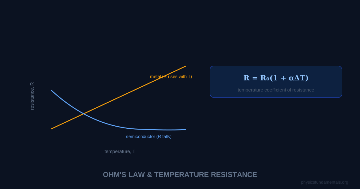
The resistance of a metal increases with temperature according to R = R₀(1 + αΔT), where R₀ is the resistance at reference temperature T₀, α is the temperature coefficient of resistance (°C⁻¹ or K⁻¹), and ΔT is the temperature change. This linear relationship holds well over modest temperature ranges. Semiconductors behave oppositely — their resistance decreases steeply as temperature rises, because thermal energy liberates more charge carriers. This opposite behaviour makes semiconductors invaluable as temperature sensors (NTC thermistors) and switching devices.
Understanding why resistance changes with temperature requires thinking about what causes resistance at the microscopic level — the collisions between drifting electrons and vibrating lattice ions. In metals, more vibration means more collisions means more resistance. In semiconductors, more thermal energy means more charge carriers available — and this effect dominates, reducing resistance.
- Why metal resistance increases with temperature (microscopic explanation)
- R = R₀(1 + αΔT): temperature coefficient and its values for common metals
- Why semiconductor resistance decreases with temperature
- NTC thermistors and LDRs — practical applications
- Superconductivity — resistance drops to exactly zero below T_c
- 4 worked examples with temperature and resistance calculations
Why Temperature Affects Resistance
In metals: Resistance arises from electrons colliding with vibrating lattice ions as they drift through the conductor. At higher temperatures, ions vibrate with greater amplitude — presenting a larger "target" and causing more collisions per unit time. Each collision impedes electron drift, so resistance increases.
In semiconductors: At low temperatures, few electrons have enough energy to break free from atomic bonds and become conduction electrons. As temperature rises, thermal energy liberates more electrons into the conduction band. The increase in charge carrier number dominates over the increase in collision rate, so overall resistance decreases.
Metal Resistance: R = R₀(1 + αΔT)
Where:
- R = resistance at temperature T (Ω)
- R₀ = resistance at reference temperature T₀ (usually 20°C or 0°C) (Ω)
- α = temperature coefficient of resistance (°C⁻¹ or K⁻¹)
- ΔT = T − T₀ (temperature change)
| Material | α (×10⁻³ per °C) | ρ at 20°C (Ω·m) |
|---|---|---|
| Copper | 3.9 | 1.72 × 10⁻⁸ |
| Aluminium | 4.3 | 2.82 × 10⁻⁸ |
| Tungsten | 4.5 | 5.60 × 10⁻⁸ |
| Iron | 6.0 | 1.00 × 10⁻⁷ |
| Nichrome | 0.4 | 1.10 × 10⁻⁶ |
Nichrome (nickel-chromium alloy) has a very low α — its resistance barely changes with temperature — which is why it's used in heating elements and resistance wires where stable resistance is needed.
NTC Thermistors
NTC (Negative Temperature Coefficient) thermistors are semiconductor resistors whose resistance decreases significantly with increasing temperature — the opposite of metals. A typical NTC thermistor might change from 100 kΩ at 0°C to 1 kΩ at 50°C — a hundredfold change over 50 degrees.
Applications: temperature sensing in ovens, computers (CPU temperature monitoring), medical thermometers, and fire alarm systems. In a potential divider circuit, a thermistor produces a voltage that varies with temperature — this voltage can trigger circuits or be read by a microcontroller.
LDRs (Light-Dependent Resistors)
LDRs work on a similar principle: in the dark, few electrons are excited into the conduction band, so resistance is high (typically MΩ). In bright light, photons excite electrons into the conduction band, reducing resistance to a few hundred Ω. Used in automatic street lights, camera exposure meters, and alarm systems.
Superconductivity
Some materials undergo a phase transition below a critical temperature T_c where resistance drops to exactly zero — superconductivity. In a superconductor, electron pairs (Cooper pairs) form and propagate without any scattering. A current started in a superconducting ring persists indefinitely without any voltage source.
Critical temperatures: Mercury (Hg): T_c = 4.2 K; Niobium (Nb): T_c = 9.3 K; YBCO ceramic: T_c = 92 K (liquid nitrogen temperature). Applications: MRI magnets, particle accelerators (CERN's superconducting magnets), maglev trains, and quantum computing.
4 Worked Examples
Example 1 — Tungsten filament resistance
Problem: A tungsten light bulb filament has resistance 30 Ω at 20°C. Find its resistance at 2520°C, the operating temperature. (α = 4.5 × 10⁻³ °C⁻¹)
Solution:
ΔT = 2520 − 20 = 2500°C
R = R₀(1 + αΔT) = 30 × (1 + 4.5 × 10⁻³ × 2500)
= 30 × (1 + 11.25) = 30 × 12.25 = 367.5 Ω
The filament resistance increases more than 12× between cold and operating temperature — this is why light bulbs draw large surge currents when first switched on.
Example 2 — Finding temperature from resistance
Problem: A copper wire has resistance 10 Ω at 20°C. At what temperature is its resistance 12 Ω? (α_Cu = 3.9 × 10⁻³ °C⁻¹)
Solution:
12 = 10(1 + 3.9 × 10⁻³ × ΔT)
1.2 = 1 + 3.9 × 10⁻³ × ΔT
ΔT = 0.2/(3.9 × 10⁻³) = 51.3°C
T = 20 + 51.3 = 71.3°C
Example 3 — Temperature coefficient calculation
Problem: A resistor measures 50 Ω at 0°C and 57.5 Ω at 150°C. Find its temperature coefficient.
Solution:
57.5 = 50(1 + α × 150)
1.15 = 1 + 150α
α = 0.15/150 = 1.0 × 10⁻³ °C⁻¹
Example 4 — Thermistor in a potential divider
Problem: A NTC thermistor (R_T = 10 kΩ at 20°C) is in series with a 10 kΩ fixed resistor across 6 V. Find the voltage across the fixed resistor at 20°C, and qualitatively describe what happens as temperature increases.
Solution:
At 20°C: both resistors equal → voltage divides equally
V_fixed = 6 × 10/(10 + 10) = 3 V
As temperature increases: R_T decreases → more voltage drops across the fixed resistor → V_fixed increases. This increasing voltage can trigger a circuit when temperature exceeds a threshold.
Resistivity and Its Temperature Dependence
The resistance of a conductor depends on its material (resistivity ρ), length L, and cross-sectional area A:
Resistivity ρ itself varies with temperature. For metals, the linear approximation is:
Which gives the familiar R = R₀(1 + αΔT) once multiplied by L/A. This linear relationship holds well from cryogenic temperatures up to several hundred degrees for most metals; at very high temperatures the relationship becomes sublinear as the lattice structure changes.
Microscopic Origins of Resistance
Resistance in a metal arises from two main sources:
- Thermal (phonon) scattering: conduction electrons collide with thermally vibrating lattice ions. At higher temperatures, lattice vibrations have larger amplitude → more frequent/energetic collisions → electrons lose more momentum → higher resistance. This is the dominant mechanism at room temperature and above, giving the linear increase with T.
- Impurity scattering: electrons collide with impurity atoms, vacancies, and grain boundaries. This contribution is temperature-independent and determines the residual resistance at very low temperatures (as thermal vibrations → 0). Perfectly pure, defect-free crystals have very low residual resistance; real commercial conductors have residual resistance set by their purity.
The total resistivity is approximately the sum of both contributions (Matthiessen's rule): ρ(T) = ρ_thermal(T) + ρ_residual.
Semiconductors — Band Theory Explanation
In a semiconductor, electrons must cross an energy gap (band gap) to become free charge carriers. At T = 0 K, no electrons have enough energy — resistance is infinite. As temperature rises, more electrons are thermally excited across the gap: n_carriers ∝ e^(−E_gap/2kT), where k is Boltzmann's constant. The number of charge carriers increases exponentially with temperature. Since conductivity σ = nqμ (n = carrier density, q = charge, μ = mobility), and n increases much faster than mobility μ decreases, the overall resistance falls steeply with temperature.
For silicon: E_gap = 1.12 eV at room temperature. At 300 K: n ≈ 10¹⁰ cm⁻³. At 400 K: n ≈ 10¹² cm⁻³ — a hundred-fold increase in 100 K. This exponential sensitivity to temperature is why semiconductor devices are rated for maximum operating temperatures and why computer chips need cooling.
Worked Example 5 — Thermistor in a circuit
Problem: An NTC thermistor has resistance 4.7 kΩ at 20°C and 1.2 kΩ at 60°C. It is connected in series with a 2.2 kΩ resistor across a 5 V supply. Find the output voltage across the fixed resistor at each temperature.
Solution:
At 20°C: I = 5/(4700 + 2200) = 5/6900 = 7.25 × 10⁻⁴ A
V_out = I × 2200 = 7.25 × 10⁻⁴ × 2200 = 1.59 V
At 60°C: I = 5/(1200 + 2200) = 5/3400 = 1.47 × 10⁻³ A
V_out = 1.47 × 10⁻³ × 2200 = 3.24 V
The output voltage has more than doubled as temperature rose from 20°C to 60°C — this voltage change is large enough to trigger a comparator circuit or be read by an ADC as a temperature measurement.
Superconductivity — Zero Resistance Below T_c
Some materials undergo a phase transition below a critical temperature T_c where resistance drops discontinuously to exactly zero — not just very low, but zero. Conventional superconductors (Hg, Pb, Nb) have T_c below 20 K; high-temperature superconductors (YBCO ceramics) have T_c up to 138 K (−135°C), achievable with liquid nitrogen. The BCS theory (Bardeen, Cooper, Schrieffer, 1957 Nobel Prize) explains conventional superconductivity through Cooper pairs: two electrons with opposite momenta and spins form a weakly bound pair through lattice-mediated phonon exchange. Cooper pairs are bosons and condense into a single macroscopic quantum state — they flow without scattering and therefore without resistance.
A current circulating in a superconducting ring persists indefinitely — experiments have confirmed stability for years with no measurable decay. This is exploited in: MRI magnets (1.5–7 T fields sustained without continuous power input once the magnet is charged); particle accelerator bending magnets (LHC uses 1,232 dipole magnets, each 15 m long, operating at 1.9 K); and prototype fusion reactor magnets (ITER uses 10,000 tonnes of superconducting cable to confine plasma magnetically).
Light-Dependent Resistors (LDRs)
An LDR (also called a photoresistor) uses the photoconductive effect: photons excite electrons across the band gap of cadmium sulphide (CdS), increasing the carrier density and decreasing resistance. In darkness: resistance ~1 MΩ. In bright sunlight: resistance ~100 Ω — a 10,000-fold change. The response time is relatively slow (~10–100 ms), making LDRs unsuitable for fast switching but adequate for ambient light sensing. Used in automatic street lights (switching off when ambient light rises above threshold), camera exposure meters, alarm systems (beam interruption detectors), and garden solar-powered lights.
Worked Example 6 — Finding temperature from resistance ratio
Problem: An iron wire has resistance R₁ at T₁ = 0°C. At T₂, the resistance is 2.5 times R₁. Find T₂. (α_Fe = 6.0 × 10⁻³ °C⁻¹)
Solution:
R₂/R₁ = 1 + αΔT → 2.5 = 1 + 6.0 × 10⁻³ × (T₂ − 0)
1.5 = 6.0 × 10⁻³ × T₂ → T₂ = 1.5/(6.0 × 10⁻³) = 250°C
Temperature Coefficient Table and Applications
| Material | α (×10⁻³ °C⁻¹) | Typical application |
|---|---|---|
| Copper | 3.9 | Power cables, motor windings |
| Aluminium | 4.3 | Overhead transmission lines |
| Tungsten | 4.5 | Light bulb filaments |
| Nichrome | 0.4 | Heating elements, resistance wire |
| Platinum | 3.9 | Precision resistance thermometry (PRT) |
Platinum resistance thermometers (PRTs) exploit the precisely linear α of platinum to measure temperature with 0.001°C accuracy from −200°C to +850°C. The ITS-90 international temperature scale uses PRTs as the primary interpolation standard between fixed points (triple point of water, freezing point of silver, etc.). The linear formula R = R₀(1 + αΔT) is accurate enough that PRTs define the most precise temperature measurements in the world.
Exam Summary
Metal resistance increases with temperature: R = R₀(1 + αΔT), α typically 3–6 × 10⁻³ °C⁻¹. Semiconductor (NTC thermistor) resistance decreases sharply with temperature — exponential decrease due to exponentially increasing carrier density. LDR resistance decreases with increasing light intensity. Superconductors have exactly zero resistance below T_c. For exam calculations: identify whether the material is a metal (use linear formula) or semiconductor (qualitative decrease). Common exam questions: find R at a new temperature; find the temperature from a new resistance; analyse a potential divider with a thermistor to find V_out as temperature changes.
The temperature dependence of resistance is not merely an academic curiosity — it is the basis of a huge range of practical devices. Every temperature sensor in your smartphone, washing machine, car engine, and home thermostat uses a thermistor or platinum resistance thermometer. The heating element in a kettle, toaster, and electric oven is made from nichrome precisely because its low α means resistance stays stable across the wide temperature range of its operation. The superconducting magnets in every MRI scanner, every particle accelerator, and every magnetically levitated train exploit the zero-resistance state below T_c. Understanding how and why resistance changes with temperature — at the microscopic level of electron scattering — connects to the entire field of condensed matter physics that underlies modern materials science and electronics.
In exam questions on resistance and temperature, three scenario types appear: (1) find R at a new T given R₀ and α — direct substitution into R = R₀(1 + αΔT); (2) find T from a measured R — rearrange for ΔT = (R/R₀ − 1)/α; (3) describe and explain the behaviour of an NTC thermistor, LDR, or superconductor qualitatively. For type (3): NTC thermistor → more thermal energy → more carriers excited → resistance decreases (non-linearly, steeply). LDR → more photons → more carriers excited → resistance decreases. Superconductor → below T_c, Cooper pairs form, zero scattering → exactly zero resistance. Always state the microscopic mechanism, not just the macroscopic effect.
The resistance-temperature relationship is one of the most practically important phenomena in all of electrical engineering. Every electrical system that operates across a range of temperatures — from automotive wiring (−40°C to +150°C) to aerospace electronics (−55°C to +125°C) to Arctic and desert telecommunications infrastructure — must account for how conductor resistance changes with temperature. Engineers must size cables for the worst-case resistance (highest operating temperature → highest resistance → highest voltage drop and power loss); protection systems must account for how fault current changes as conductor temperature rises during a fault. The simple formula R = R₀(1 + αΔT) underlies all of this analysis.
Frequently Asked Questions
Why does resistance increase with temperature in metals?
Why do semiconductors have lower resistance at higher temperatures?
What is an NTC thermistor?
What is superconductivity?
What material is used for heating elements and why?
Share this article
Written by
Physics Fundamentals Editorial Team
Written and reviewed by our team of physics educators. Content is aligned with A-Level, GCSE, AP Physics, and undergraduate curricula.
About Physics Fundamentals →