Kirchhoff's laws are two rules that govern every electric circuit. Kirchhoff's Current Law (KCL) states that the total current entering a junction equals the total current leaving it. Kirchhoff's Voltage Law (KVL) states that the sum of all voltages around any closed loop in a circuit is zero. Together they let you find the current and voltage at every point in any circuit, no matter how complex.
These laws aren't approximations — they're consequences of two fundamental conservation principles: KCL follows from conservation of charge, and KVL follows from conservation of energy. Published by Gustav Kirchhoff in 1845 when he was just 21 years old, they remain the foundation of circuit analysis in everything from household wiring to microprocessor design.
- KCL: current at junctions — the sum rule and how to apply it
- KVL: voltage around loops — sign conventions and the loop equation
- Series circuits: same current, voltages add
- Parallel circuits: same voltage, currents add
- 4 fully worked examples including multi-loop circuits
Basic Circuit Quantities
Before applying Kirchhoff's laws, you need three quantities clearly defined:
- Current (I) — the rate of flow of charge, measured in amperes (A). 1 A = 1 coulomb per second. Current flows from higher potential to lower potential in a circuit (conventional current direction).
- Voltage (V) — the potential difference between two points, measured in volts (V). A battery maintains a potential difference across its terminals. Resistors cause a voltage drop in the direction of current flow.
- Resistance (R) — opposition to current flow, measured in ohms (Ω). From Ohm's law: V = IR, so R = V/I.
Kirchhoff's Current Law (KCL)
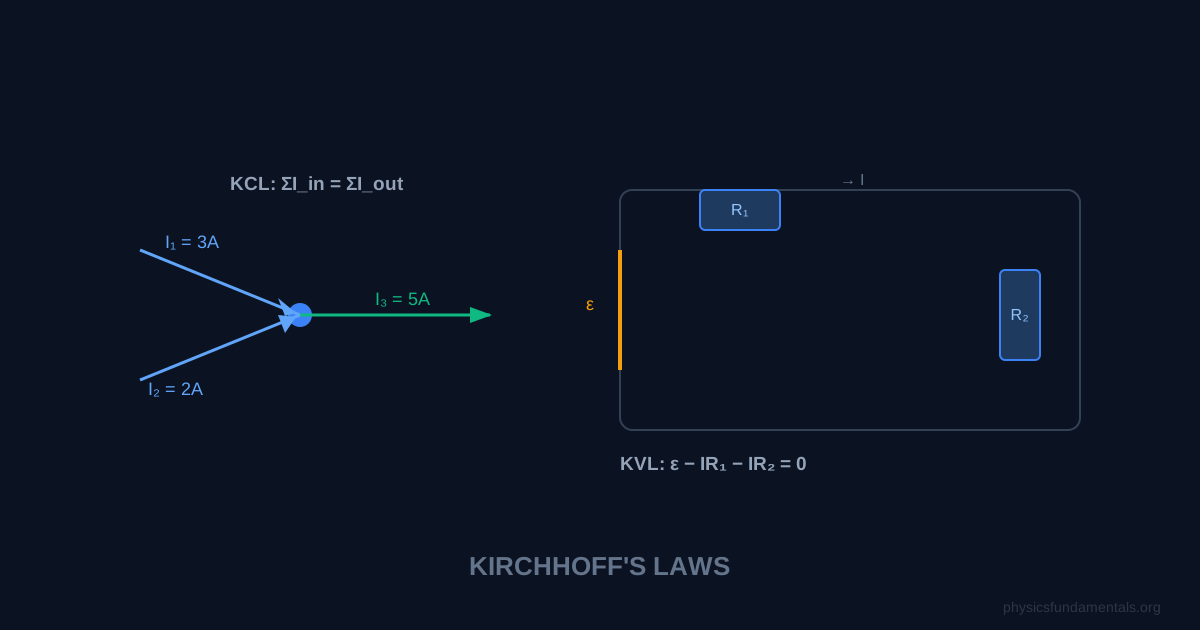
The algebraic sum of all currents at any node (junction) in a circuit is zero.
In plain terms: whatever current flows into a junction must flow out of it. Charge cannot accumulate at a node in a steady-state circuit. If three wires meet at a junction with currents I₁ (in), I₂ (in), and I₃ (out), then: I₁ + I₂ = I₃.
Sign convention: Choose a direction (usually: currents entering the node are positive, currents leaving are negative). Sum all currents at the node and set equal to zero. The algebra handles the rest.
KCL in series vs parallel
In a series circuit, there are no junctions — the same current flows through every element. KCL is satisfied trivially: one wire in, one wire out, same current throughout.
In a parallel circuit, the main current splits at each junction. KCL tells you exactly how it splits: the sum of branch currents equals the total current entering the parallel section.
Kirchhoff's Voltage Law (KVL)
The algebraic sum of all voltages around any closed loop in a circuit is zero.
This follows from conservation of energy: if you travel around a complete loop and return to your starting point, the net work done per unit charge must be zero — you're back where you started.
Sign convention for KVL:
- Choose a direction to traverse the loop (clockwise or anticlockwise — your choice, the answer is the same).
- When you cross a resistor in the direction of assumed current flow: voltage drops (−IR).
- When you cross a resistor against the direction of assumed current flow: voltage rises (+IR).
- When you cross a battery from − to + terminal: voltage rises (+EMF).
- When you cross a battery from + to − terminal: voltage drops (−EMF).
- Sum all rises and drops. Set equal to zero.
Series Circuits
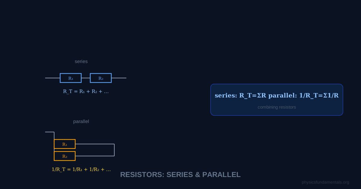
In a series circuit, components are connected end-to-end in a single path. All current must flow through every component.
Key rules for series circuits:
- Current is the same through all components: I₁ = I₂ = I₃ = I
- Voltages add: V_total = V₁ + V₂ + V₃
- Resistances add: R_total = R₁ + R₂ + R₃
From KVL on a series loop with battery EMF ε and resistors R₁, R₂:
Parallel Circuits
In a parallel circuit, components share the same two nodes. Each branch has the same voltage across it.
Key rules for parallel circuits:
- Voltage is the same across all branches: V₁ = V₂ = V₃ = V
- Currents add: I_total = I₁ + I₂ + I₃
- Reciprocals of resistance add: 1/R_total = 1/R₁ + 1/R₂ + 1/R₃
For two resistors in parallel, the equivalent resistance simplifies to:
4 Worked Examples
Example 1 — Series circuit
Problem: A 12 V battery is connected to two resistors in series: R₁ = 4 Ω and R₂ = 8 Ω. Find: (a) total resistance, (b) current, (c) voltage across each resistor.
Solution:
(a) R_total = 4 + 8 = 12 Ω
(b) I = V/R = 12/12 = 1 A
(c) V₁ = IR₁ = 1 × 4 = 4 V; V₂ = IR₂ = 1 × 8 = 8 V
Check (KVL): 12 − 4 − 8 = 0 ✓
Example 2 — Parallel circuit
Problem: A 6 V battery connects to two parallel resistors: R₁ = 6 Ω and R₂ = 12 Ω. Find: (a) equivalent resistance, (b) total current, (c) current through each resistor.
Solution:
(a) R_eq = (6 × 12)/(6 + 12) = 72/18 = 4 Ω
(b) I_total = V/R_eq = 6/4 = 1.5 A
(c) I₁ = V/R₁ = 6/6 = 1 A; I₂ = V/R₂ = 6/12 = 0.5 A
Check (KCL): 1 + 0.5 = 1.5 A ✓
Example 3 — KCL at a junction
Problem: At a junction, currents I₁ = 3 A and I₂ = 2 A flow in. Current I₃ flows out in one branch and I₄ = 1 A flows out in another. Find I₃.
Solution:
KCL: ΣI_in = ΣI_out
3 + 2 = I₃ + 1
I₃ = 4 A
Example 4 — Multi-loop circuit with KVL
Problem: A circuit has a 9 V battery, a 3 Ω resistor (R₁) in series with a parallel combination of R₂ = 6 Ω and R₃ = 6 Ω. Find the current through R₁ and each parallel branch.
Solution:
Step 1 — Parallel equivalent: R₂₃ = (6 × 6)/(6 + 6) = 3 Ω
Step 2 — Total resistance: R_total = R₁ + R₂₃ = 3 + 3 = 6 Ω
Step 3 — Total current (through R₁): I = 9/6 = 1.5 A
Step 4 — Voltage across parallel section: V₂₃ = I × R₂₃ = 1.5 × 3 = 4.5 V
Step 5 — Branch currents: I₂ = 4.5/6 = 0.75 A; I₃ = 4.5/6 = 0.75 A
Check (KCL): 0.75 + 0.75 = 1.5 A ✓
Check (KVL): 9 − (1.5 × 3) − 4.5 = 9 − 4.5 − 4.5 = 0 ✓
Internal Resistance
Real batteries have internal resistance r — a small resistance inside the battery itself that causes the terminal voltage to drop when current flows:
Where EMF is the electromotive force (the battery's "ideal" voltage). Applying KVL to a circuit with internal resistance:
A battery with EMF = 12 V and r = 0.5 Ω connected to R = 11.5 Ω: I = 12/(11.5 + 0.5) = 1 A. Terminal voltage = 12 − (1 × 0.5) = 11.5 V — 0.5 V is "lost" across the internal resistance.
Internal Resistance and Terminal Voltage
Real batteries and power supplies have internal resistance r — a small resistance inside that causes the terminal voltage to fall when current is drawn. The circuit equation (KVL around a loop with EMF ε, internal resistance r, and external resistance R):
The terminal voltage is always less than the EMF when current flows. This explains why a battery-powered torch dims as the battery discharges — internal resistance increases as the electrolyte is consumed, causing terminal voltage to fall even as the EMF barely changes. A car battery rated 12 V may only deliver 10 V at the high currents needed by the starter motor (hundreds of amps), because V = ε − Ir = 12 − (r × hundreds) drops significantly.
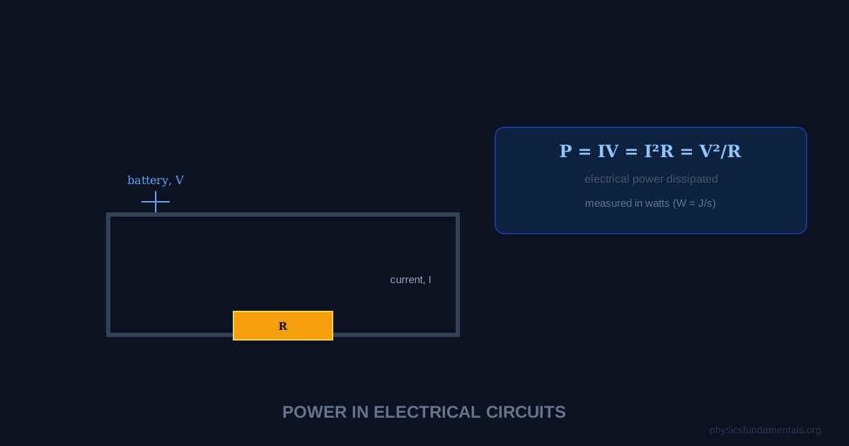
Worked example: A battery has EMF 9 V and internal resistance 0.5 Ω. A 4.5 Ω resistor is connected. Find: (a) current, (b) terminal voltage, (c) power wasted in internal resistance.
(a) I = ε/(R + r) = 9/(4.5 + 0.5) = 9/5 = 1.8 A
(b) V_terminal = ε − Ir = 9 − 1.8 × 0.5 = 9 − 0.9 = 8.1 V
(c) P_internal = I²r = 1.8² × 0.5 = 3.24 × 0.5 = 1.62 W
Potential Dividers
Two resistors in series form a potential divider — the circuit used everywhere in electronics for setting reference voltages, biasing transistors, and reading sensors. The output voltage V_out across R₂:
This is KVL applied directly: the current I = V_in/(R₁ + R₂) is the same through both; the voltage across R₂ is V_out = IR₂ = V_in × R₂/(R₁ + R₂).
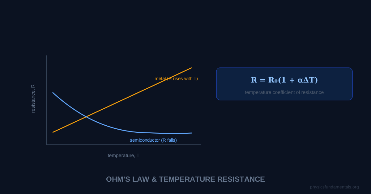
Replacing R₂ with a thermistor or LDR makes the output voltage vary with temperature or light. At high temperature (low thermistor resistance), V_out decreases. This voltage can be compared with a reference voltage by a comparator circuit to trigger an alarm or switch a heater. The potential divider is the basis of virtually all analogue sensor circuits.
Measuring Instruments and Their Effects on Circuits
Ideal measuring instruments don't disturb the circuit: an ideal voltmeter has infinite resistance (draws no current), an ideal ammeter has zero resistance (causes no voltage drop). Real instruments deviate from this:
- Voltmeter (resistance R_V): connected in parallel with a component. The combination has resistance R_component × R_V/(R_component + R_V) — less than R_component, so the voltmeter loads the circuit and reads slightly low. For accurate readings: R_V >> R_component.
- Ammeter (resistance R_A): connected in series. Adds resistance R_A, reducing the current it's trying to measure. For accurate readings: R_A << R_circuit.
Digital multimeters typically have R_V ≈ 10 MΩ (excellent for most circuits) and R_A ≈ 0.1–1 Ω (fine for circuits with total resistance >> 1 Ω, problematic for very low-resistance circuits).
Worked Example 5 — Wheatstone bridge balanced condition
Problem: In a Wheatstone bridge, R₁ = 100 Ω, R₂ = 200 Ω, R₃ = 150 Ω. Find the value of R₄ for a balanced bridge (no current through the galvanometer).
Solution:
At balance: R₁/R₂ = R₃/R₄ (the balance condition, derived from KCL and KVL)
R₄ = R₃ × R₂/R₁ = 150 × 200/100 = 300 Ω
Check: R₁/R₂ = 100/200 = 0.5; R₃/R₄ = 150/300 = 0.5 ✓
Kirchhoff's Laws in AC Circuits
KCL and KVL apply to AC circuits as well as DC, though the analysis becomes more complex because voltage and current are sinusoidally varying and generally not in phase. In AC circuits, resistors cause no phase shift (V and I in phase), capacitors cause a 90° phase lag (I leads V), and inductors cause a 90° phase lead (I lags V). Despite this complexity, KCL (Σi = 0 at every instant) and KVL (Σv = 0 around every loop at every instant) remain exactly true throughout the cycle, forming the basis of AC circuit analysis and phasor diagrams.
Exam Strategy for Circuit Problems
For simple series-parallel circuits: identify which components are in series (same current) and which are in parallel (same voltage), simplify step by step. For multi-loop circuits that cannot be simplified: use the systematic KCL/KVL method. The number of independent equations you need equals the number of unknown currents: for a circuit with b branches and n nodes, write (n−1) KCL equations and (b−n+1) KVL loop equations. Solve using substitution or matrix methods. Always check your answer: sum of powers dissipated = power delivered by all sources. If any current comes out negative, reverse its arrow on the diagram — the magnitude is correct, only the assumed direction was wrong.
Common pitfalls: (1) applying series/parallel rules to circuits that don't simplify that way — always check the topology first; (2) incorrect signs when writing KVL — draw the current direction arrows before writing equations; (3) forgetting internal resistance in battery problems — the EMF is not the same as terminal voltage when current flows. Practice drawing the free-body diagram equivalent for circuits: a clear circuit sketch with all currents and their assumed directions, annotated with component values, before writing a single equation.
Kirchhoff's laws are ultimately conservation laws: KCL enforces conservation of charge (no charge accumulates at junctions in steady state) and KVL enforces conservation of energy (no work is done moving a charge around a closed loop in a static field). They are exact laws — not approximations — and apply at every instant, at every junction, and around every loop in any electrical circuit. Their range of validity extends from household wiring through to circuits operating at gigahertz frequencies, where distributed capacitance and inductance require modifications, and ultimately to the lumped-element approximation breaking down at microwave and optical frequencies where full electromagnetic field theory is needed.
Frequently Asked Questions
What is Kirchhoff's current law?
What is Kirchhoff's voltage law?
What is the difference between series and parallel circuits?
How do you apply KVL to a circuit?
Why is parallel resistance less than series resistance?
Share this article
Written by
Physics Fundamentals Editorial Team
Written and reviewed by our team of physics educators. Content is aligned with A-Level, GCSE, AP Physics, and undergraduate curricula.
About Physics Fundamentals →