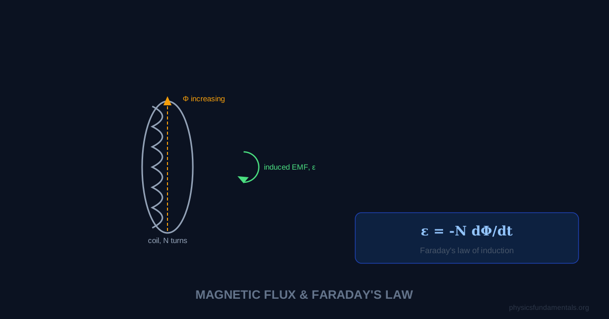
Magnetic flux (Φ) measures how much magnetic field passes through a given area: Φ = BAcosθ, where B is the magnetic field strength (tesla), A is the area (m²), and θ is the angle between the field and the normal to the surface. Faraday's law then states that any change in this flux induces an electromotive force (EMF): EMF = −N × dΦ/dt, where N is the number of turns in a coil. The negative sign is Lenz's law — the induced EMF opposes the change that caused it.
Together these ideas explain how every electrical generator works. Rotate a coil in a magnetic field, continuously changing the flux through it, and you get a continuously induced EMF — alternating current. Every power station, every bicycle dynamo, every wind turbine operates on this principle discovered by Michael Faraday in 1831.
- Magnetic flux Φ = BAcosθ — definition, units (webers), and the angle factor
- Faraday's law: EMF = −NdΦ/dt — derived and explained
- Lenz's law — why the negative sign matters and how to apply it
- 4 worked examples including rotating coils and changing B fields
- How generators and transformers use electromagnetic induction
Magnetic Flux: Φ = BAcosθ
Where:
- Φ = magnetic flux, in webers (Wb); 1 Wb = 1 T·m²
- B = magnetic flux density (field strength), in tesla (T)
- A = area of the surface, in m²
- θ = angle between B and the normal to the surface
When B is perpendicular to the surface (θ = 0°): Φ = BA (maximum). When B is parallel to the surface (θ = 90°): Φ = 0 (no field lines pass through). Flux is maximum when field lines are perpendicular to the area.
Faraday's Law: EMF = −N dΦ/dt
The induced EMF in a coil of N turns equals minus N times the rate of change of flux through one turn. Units: volts (V) = webers per second (Wb/s).
For a uniform change in flux over time Δt: EMF = −N × ΔΦ/Δt.
Flux linkage NΦ combines the number of turns and flux into a single quantity. Faraday's law becomes: EMF = −d(NΦ)/dt.
Lenz's Law — the Negative Sign
The negative sign encodes Lenz's law: the induced EMF acts in a direction that opposes the change in flux that produced it. This is conservation of energy in disguise — if the induced current reinforced the change, you'd get a runaway increase in flux and a free energy source, which thermodynamics forbids.
Practical rule: if flux through a coil is increasing, the induced current flows in a direction to create a magnetic field opposing the increase (opposing B). If flux is decreasing, the induced current tries to maintain it (same direction as B).
4 Worked Examples
Example 1 — Flux through a coil
Problem: A circular coil of radius 0.1 m sits in a 0.5 T field. The field makes 30° with the normal to the coil. Find the magnetic flux.
Solution:
A = π × 0.1² = 0.03142 m²
Φ = BAcosθ = 0.5 × 0.03142 × cos30° = 0.5 × 0.03142 × 0.866 = 0.0136 Wb
Example 2 — Induced EMF from changing field
Problem: A 200-turn coil has area 0.05 m². The magnetic field through it increases uniformly from 0.2 T to 0.8 T in 0.4 s. Find the induced EMF.
Solution:
ΔΦ = ΔB × A = (0.8 − 0.2) × 0.05 = 0.03 Wb
EMF = N × ΔΦ/Δt = 200 × 0.03/0.4 = 15 V
Example 3 — Rotating coil generator
Problem: A 100-turn rectangular coil (area 0.02 m²) rotates at 50 Hz in a 0.3 T field. Find the peak EMF.
Solution:
Peak EMF = NBAω = NBA × 2πf
= 100 × 0.3 × 0.02 × 2π × 50 = 100 × 0.3 × 0.02 × 314.2 = 188.5 V
Example 4 — Flux change direction
Problem: A north pole is moved toward a horizontal coil (faces up). The flux through the coil increases. In what direction does the induced current flow when viewed from above?
Solution:
By Lenz's law, the induced current opposes the increasing downward flux. It must create an upward field through the coil (opposing B from the approaching north pole). By the right-hand rule, this requires the current to flow anticlockwise when viewed from above.
Generators and Transformers
AC Generator: A coil rotates in a uniform magnetic field. As it rotates, the angle θ changes, so flux Φ = BAcosθ changes sinusoidally, inducing a sinusoidal EMF: EMF = NBAω sin(ωt). This is how mains electricity is generated at power stations.
Transformer: An alternating current in a primary coil (N_p turns) creates a changing flux in an iron core. This same changing flux passes through a secondary coil (N_s turns), inducing an EMF. The voltage ratio: V_s/V_p = N_s/N_p. Transformers work on AC only — DC produces no changing flux and no induced EMF.
Faraday's Law — Quantitative Statement
Faraday's law gives the magnitude of the induced EMF:
For a changing flux through N turns. In calculus form:
The negative sign is Lenz's law. The flux Φ = BA cosθ, where θ is the angle between B and the normal to the coil area A. EMF can be induced by changing B (electromagnets switching on/off), changing A (a loop being deformed), or changing θ (rotating coil in a generator — the standard way AC is generated).
AC Generators — Rotating Coil in a Magnetic Field
In an AC generator, a rectangular coil of N turns and area A rotates at angular velocity ω in a uniform field B. The flux through the coil:
The induced EMF (from Faraday's law, EMF = −NdΦ/dt):
Where EMF₀ = NBAω is the peak EMF. The coil is zero EMF when face-on to the field (flux is maximum, rate of change is zero) and maximum EMF when edge-on to the field (flux is zero, rate of change is maximum). The AC generator equation connects the peak output voltage directly to the design parameters: number of turns N, coil area A, field strength B, and rotation speed ω.
Worked Example 5 — AC generator
Problem: A generator has a coil with 200 turns, area 0.05 m², rotating at 50 Hz in a 0.08 T field. Find: (a) the peak EMF, (b) the rms EMF.
Solution:
ω = 2πf = 2π × 50 = 314.2 rad/s
(a) EMF₀ = NBAω = 200 × 0.08 × 0.05 × 314.2 = 251.3 V
(b) EMF_rms = EMF₀/√2 = 251.3/1.414 = 177.7 V
Transformers — Mutual Flux Induction
A transformer works by electromagnetic induction. The primary coil carries AC current, creating a time-varying flux in the iron core. This flux threads through the secondary coil, inducing an EMF by Faraday's law:
An ideal transformer conserves power: V_p I_p = V_s I_s (no losses). Real transformers have efficiency 95–99%, with losses from:
- Copper losses: I²R heating in the winding resistance — minimised by using thick copper wire
- Iron (core) losses: eddy currents and hysteresis heating in the core — minimised by laminating the core (thin insulated sheets prevent large eddy current loops) and using silicon steel (low hysteresis)
- Flux leakage: flux that doesn't link both coils — minimised by winding both coils on the same limb of the core
Electromagnetic Induction in Nature
Faraday's law operates throughout nature. The Earth's magnetic field is maintained by electromagnetic induction in its liquid iron outer core — the geodynamo. Convecting molten iron generates current loops; these currents create magnetic fields; the fields induce more currents in the flowing conductor. This self-sustaining process has maintained Earth's field for billions of years and reverses polarity every ~300,000 years on average (the last reversal was 780,000 years ago). Sharks and rays detect prey buried in sand using electroreceptors (the ampullae of Lorenzini) that sense the tiny electrical currents generated by moving muscle — the muscles moving in Earth's magnetic field induce currents by Faraday's law, betraying the prey's location to within millimetres.
Worked Example 6 — EMF from a moving rod
Problem: A conducting rod of length 0.4 m moves at 5 m/s perpendicular to a 0.3 T uniform magnetic field. Find the induced EMF and the current if the rod has resistance 2 Ω and forms a closed circuit with the rails.
Solution:
As the rod moves, the area swept per second = L × v = 0.4 × 5 = 0.2 m²/s
Rate of change of flux = B × (dA/dt) = 0.3 × 0.2 = 0.06 Wb/s
EMF = dΦ/dt = 0.06 V = 60 mV
I = EMF/R = 0.06/2 = 0.03 A = 30 mA
Alternatively: EMF = BLv = 0.3 × 0.4 × 5 = 0.06 V — the motional EMF formula, directly from Faraday's law for a moving conductor.
Eddy Current Applications
Faraday's law drives eddy currents in bulk conductors exposed to changing magnetic fields. These currents dissipate energy (I²R) and experience forces (F = BIL). Useful applications: induction heating (eddy currents in a metal workpiece heat it — used in industrial forging and induction cooking hobs); induction motors (rotating magnetic field induces eddy currents in a conducting rotor, which experience forces driving rotation — the most common industrial motor, with no brushes or commutator); eddy current testing (detecting cracks or voids in metals by measuring how defects alter the eddy current pattern). Harmful: eddy currents waste energy in transformer cores (reduced by lamination) and in the cores of high-frequency inductors (reduced by using ferrite — a ceramic with high resistivity).
Exam Summary for Faraday's Law
Key formula: |EMF| = NΔΦ/Δt = N × d(BA cosθ)/dt. Flux Φ = BA cosθ (maximum when B perpendicular to plane, zero when B parallel to plane). EMF is maximum when flux is changing fastest — i.e. when dΦ/dt is maximum, not when Φ is maximum. For a rotating coil: Φ = NBA cosωt (maximum when face-on), EMF = NBAω sinωt (maximum when edge-on). The negative sign (EMF = −NdΦ/dt) is Lenz's law — always check direction separately from magnitude. For a moving rod in a field: EMF = BLv (motional EMF, where L is rod length and v is speed perpendicular to B).
Worked Example 7 — Solenoid EMF during switch-off
Problem: A solenoid has 1000 turns, length 0.2 m, cross-sectional area 8 × 10⁻⁴ m², and carries 5 A. The current is switched off uniformly in 0.04 s. Find the induced back-EMF.
Solution:
B inside solenoid = μ₀nI = 4π × 10⁻⁷ × (1000/0.2) × 5 = 4π × 10⁻⁷ × 5000 × 5 = 4π × 10⁻⁷ × 25,000 = 3.14 × 10⁻² T
Φ per turn = BA = 3.14 × 10⁻² × 8 × 10⁻⁴ = 2.51 × 10⁻⁵ Wb
Total flux linkage = NΦ = 1000 × 2.51 × 10⁻⁵ = 2.51 × 10⁻² Wb
|EMF| = NΔΦ/Δt = N(ΔB)A/Δt = 2.51 × 10⁻² / 0.04 = 0.628 V
By Lenz's law, this EMF acts to maintain the current in the same direction as it decays — appearing across the switch contacts as the circuit is broken.
Faraday's Discovery and Historical Context
Michael Faraday discovered electromagnetic induction in 1831, almost simultaneously with Joseph Henry in the USA. Faraday found that a changing current in one coil induced a current in a nearby coil — but only while the current was changing, not during steady flow. He systematically explored the conditions: changing the current magnitude, moving the coils, inserting iron cores. Within the same year he demonstrated the first electric generator (a copper disc rotating between magnet poles) and the transformer. Without formal mathematical training, Faraday conceived of "lines of force" filling space — the first visual representation of the concept of fields. Maxwell later turned Faraday's physical intuition into rigorous mathematics, producing Maxwell's equations and predicting electromagnetic waves. Faraday's discovery of induction is arguably the single most economically significant physics discovery in history — it is the basis of every electrical generator powering modern civilisation.
Worked Example 8 — Faraday's law with changing area
Problem: A rectangular loop (width 0.3 m) is pulled out of a 0.5 T uniform magnetic field at 2 m/s. The field exists over a 0.4 m wide region. Find the induced EMF as the loop exits the field.
Solution:
As the loop exits, the area inside the field decreases at rate dA/dt = 0.3 × 2 = 0.6 m²/s
Induced EMF = B × dA/dt = 0.5 × 0.6 = 0.3 V
Equivalently, using motional EMF: the right-hand edge of the loop is the only conductor cutting field lines; EMF = BLv = 0.5 × 0.3 × 2 = 0.3 V ✓
Electromagnetic induction connects moving magnets and currents in a beautiful symmetry: Oersted showed current makes magnetism; Faraday showed changing magnetism makes current. Maxwell formalised both into two of his four equations (Faraday's law and Ampère-Maxwell law) and showed they predict self-sustaining electromagnetic waves. The interplay between these two complementary phenomena — electricity creating magnetism, magnetism creating electricity — underpins all electrical engineering: generators produce AC by rotating coils in magnetic fields; motors do the reverse. The transformer, which has made high-voltage AC electricity transmission practical for over a century, relies on Faraday's law in the purest form: changing flux in a coil creates EMF in a nearby coil. All of modern electrical infrastructure flows from Faraday's 1831 discovery.
Try it yourself: check your own numbers with the Faraday's Law — Induced EMF Calculator, which shows the formula, the worked substitution and the answer step by step.
Frequently Asked Questions
What is magnetic flux?
What is Faraday's law of electromagnetic induction?
What is Lenz's law?
What is the unit of magnetic flux?
Why do transformers only work with AC?
Share this article
Written by
Physics Fundamentals Editorial Team
Written and reviewed by our team of physics educators. Content is aligned with A-Level, GCSE, AP Physics, and undergraduate curricula.
About Physics Fundamentals →