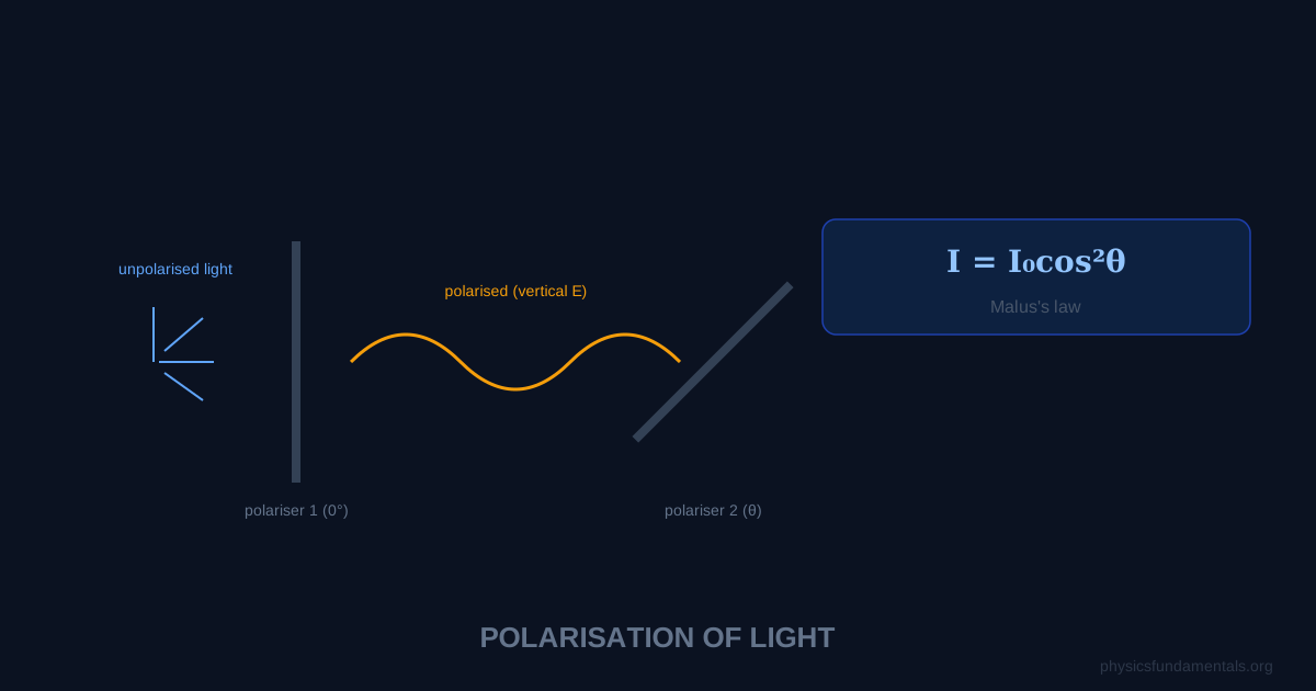
Light is a transverse electromagnetic wave, and polarisation refers to the direction of its electric field oscillation. Unpolarised light has electric field oscillations in all directions perpendicular to propagation. A polariser transmits only the component of light oscillating in one direction — the transmission axis. The intensity of polarised light passing through a second polariser (analyser) at angle θ is given by Malus's law: I = I₀cos²θ.
Only transverse waves can be polarised — this is one of the key pieces of evidence that light is a transverse wave, not a longitudinal one. Sound waves, which are longitudinal, cannot be polarised. Polarisation has enormous practical applications: polarising sunglasses reduce glare from horizontal reflective surfaces, and LCD screens use polarisation to control which pixels appear bright or dark.
- What polarisation is and why only transverse waves can be polarised
- Malus's law: I = I₀cos²θ — intensity after an analyser
- Methods of polarisation: polarisers, reflection, scattering
- Brewster's angle: tanθ_B = n₂/n₁
- 4 worked examples and applications in technology
Unpolarised vs Polarised Light
Unpolarised light (from the Sun, lamps, LEDs) has electric field vectors oscillating in all directions perpendicular to propagation — equally in all transverse directions. When this passes through a polariser, only the component aligned with the transmission axis passes through. The transmitted intensity is half the incident intensity:
Malus's Law: I = I₀cos²θ
Where I₀ is the intensity of plane-polarised light incident on an analyser (second polariser), and θ is the angle between the polarisation direction of the incident light and the transmission axis of the analyser.
- θ = 0°: I = I₀ (maximum transmission — axes aligned)
- θ = 90°: I = 0 (no transmission — crossed polarisers)
- θ = 45°: I = I₀/2 (half intensity)
Methods of Polarisation
Polaroid filters: Long polymer chains aligned in one direction absorb the component of electric field parallel to the chains, transmitting only the perpendicular component.
Reflection (Brewster's angle): When light reflects from a surface at Brewster's angle θ_B, the reflected ray is completely polarised. Brewster's angle:
For glass (n = 1.5) in air: θ_B = arctan(1.5) = 56.3°. At exactly this angle, the reflected beam is 100% polarised parallel to the surface.
Scattering: Light scattered at 90° to its direction of travel is polarised. This is why the sky is partially polarised — scattered sunlight.
4 Worked Examples
Example 1 — Malus's law basic
Problem: Plane-polarised light of intensity 80 W/m² passes through an analyser at 30° to the polarisation axis. Find the transmitted intensity.
Solution:
I = I₀cos²θ = 80 × cos²30° = 80 × 0.75 = 60 W/m²
Example 2 — Two polarisers from unpolarised light
Problem: Unpolarised light of intensity 200 W/m² passes through two polarisers with axes at 45° to each other. Find the final intensity.
Solution:
After first polariser: I₁ = 200/2 = 100 W/m²
After second polariser: I₂ = I₁cos²45° = 100 × 0.5 = 50 W/m²
Example 3 — Finding the angle
Problem: Polarised light passes through an analyser and the transmitted intensity is 25% of the incident intensity. Find the angle between the polarisation axis and the analyser.
Solution:
I/I₀ = cos²θ = 0.25 → cosθ = 0.5 → θ = 60°
Example 4 — Brewster's angle
Problem: Find Brewster's angle for light going from water (n = 1.33) to glass (n = 1.52).
Solution:
tanθ_B = n₂/n₁ = 1.52/1.33 = 1.143
θ_B = arctan(1.143) = 48.8°
Applications
Polarising sunglasses have vertically-oriented transmission axes. Sunlight reflected from horizontal surfaces (roads, water) is horizontally polarised — the sunglasses block it, reducing glare without reducing overhead light significantly.
LCD screens use two crossed polarisers with liquid crystal cells between them. Voltage applied to a cell rotates the polarisation of light passing through, allowing or blocking transmission through the second polariser — switching individual pixels on or off.
Stress analysis: Transparent materials under stress become birefringent (different refractive indices in different directions). Placing them between crossed polarisers reveals internal stress patterns as coloured interference fringes — used in engineering quality control.
Polarisation by Reflection — Brewster's Angle in Detail
When light hits a surface at Brewster's angle θ_B, the reflected ray is completely plane-polarised parallel to the surface. At this angle, the reflected and refracted rays are perpendicular (angle between them = 90°). This perpendicularity condition gives tanθ_B = n₂/n₁.
The physics: a dipole oscillating along its axis doesn't radiate in the axial direction. At Brewster's angle, the refracted ray is at 90° to the would-be reflected ray. The component of the E-field that would produce the reflected ray corresponds to dipoles oscillating along the reflection direction — and they can't radiate in that direction. Only the perpendicular component reflects, giving complete polarisation.
For glass in air (n₁ = 1, n₂ = 1.5): θ_B = arctan(1.5) = 56.3°. At exactly this angle, the reflected glare from glass surfaces is 100% polarised horizontally — which is exactly what polarising sunglasses are designed to block.
Malus's Law Derivation
When polarised light of intensity I₀ passes through a polariser (analyser) with its transmission axis at angle θ to the polarisation direction, the transmitted intensity is:
This is Malus's law (1809). The derivation: only the component of E-field parallel to the analyser's transmission axis is transmitted: E_transmitted = E₀ cosθ. Since intensity is proportional to E²: I ∝ E²_transmitted = E²₀ cos²θ → I = I₀ cos²θ.
Key values: θ = 0° → I = I₀ (maximum transmission, axes parallel); θ = 45° → I = I₀/2; θ = 90° → I = 0 (complete extinction, crossed polarisers). For unpolarised light through one polariser: the average of cos²θ over all angles is ½, so I₁ = I₀/2 regardless of polariser orientation.
Worked Example 5 — Three-polariser problem
Problem: Unpolarised light of intensity 400 W/m² passes through three polarisers. Polariser 1 is at 0°; Polariser 2 is at 30° to Polariser 1; Polariser 3 is at 90° to Polariser 1. Find the intensity after each polariser.
Solution:
After Polariser 1: I₁ = 400/2 = 200 W/m² (unpolarised → polarised, half transmitted)
After Polariser 2: I₂ = I₁ cos²30° = 200 × (0.866)² = 200 × 0.75 = 150 W/m²
After Polariser 3: θ between P2 and P3 = 90° − 30° = 60°: I₃ = I₂ cos²60° = 150 × (0.5)² = 150 × 0.25 = 37.5 W/m²
Without Polariser 2, I₃ would be 0 (crossed polarisers). Adding Polariser 2 in between allows some light through — a counterintuitive result: adding a polariser increases transmitted intensity.
Circular and Elliptical Polarisation
Linear polarisation is not the only type. In circular polarisation, the E-field vector rotates at constant magnitude — tracing a helix as the wave propagates. In elliptical polarisation, the E-field traces an ellipse. These arise when two perpendicular linearly polarised waves of equal amplitude and 90° phase difference (circular) or unequal amplitude or phase (elliptical) are combined.
Circular polarisation is used in: satellite communications (reduces the effect of antenna orientation); 3D cinema (left and right eyes receive left- and right-circularly polarised light from the screen, perceived separately through circularly polarising glasses); and radar (circularly polarised radar can distinguish weather from ground clutter, since rain drops depolarise but flat ground reflects maintaining polarisation).
Optical Activity
Some materials rotate the plane of polarisation of linearly polarised light as it passes through them — this is optical activity. It arises from chiral molecular structures (molecules that are non-superimposable on their mirror image). The rotation angle:
Where [α]_λ is the specific rotation (a material property at wavelength λ), c is concentration (g/mL), and L is path length (dm). Sucrose solution rotates polarisation clockwise (dextrorotatory, +); fructose rotates anticlockwise (levorotatory, −). A polarimeter measures the rotation angle, allowing the concentration of optically active substances to be determined without chemical analysis. The food industry uses polarimetry to measure sugar concentration in syrups; pharmaceutical companies use it to assess chiral purity of drug compounds.
Stress Analysis with Polarised Light — Photoelasticity
Certain transparent materials (glass, some plastics) become birefringent under mechanical stress — the refractive index becomes different for different polarisation directions. When such a stressed object is viewed between crossed polarisers, stress concentrations appear as coloured interference fringes (the retardation varies with wavelength, so different colours emerge at different stress levels). This technique — photoelasticity — allows engineers to visualise stress distributions in components before building physical prototypes. A 2D model of a structural component is loaded and viewed between polarised plates; the resulting fringe pattern directly maps the internal stress field. Photoelastic analysis has been used to design aircraft components, medical implants, and civil engineering structures.
Worked Example 6 — Polaroid sunglasses calculation
Problem: Sunlight (intensity 1000 W/m²) reflects from a horizontal lake surface at Brewster's angle (n_water = 1.33). The reflected light enters polarising sunglasses with transmission axis vertical. Find the intensity transmitted through the glasses.
Solution:
The reflected light is 100% horizontally polarised (Brewster reflection). The sunglasses have vertical transmission axis, so θ = 90° between polarisation direction and transmission axis.
I = I_reflected × cos²90° = I_reflected × 0 = 0 W/m²
The glasses completely block the glare. In practice, not all incident light reflects at Brewster's angle, so some non-Brewster-reflected light remains — but the glare from the water surface is eliminated.
Exam Summary for Polarisation
Polarisation is only possible for transverse waves — it is the definitive test. Light, radio waves, microwaves, and EM waves generally can all be polarised; sound (longitudinal) cannot. Key formulas: Malus's law I = I₀ cos²θ (for polarised light through a polariser at angle θ); unpolarised through one polariser → I₁ = I₀/2; Brewster's angle tanθ_B = n₂/n₁.
For the three-polariser setup: if the middle polariser is at angle θ to the first, the final transmitted intensity from unpolarised input is I₀/2 × cos²θ × cos²(90°−θ) = I₀/2 × cos²θ × sin²θ = I₀sin²(2θ)/8. This is maximum at θ = 45°, giving I₀/8 — a surprising result: the most transmission through three polarisers (first and last crossed) occurs when the middle one is at 45° to both.
Polarisation by scattering: the sky is blue because shorter wavelengths scatter more (Rayleigh scattering ∝ 1/λ⁴), and sky light is partially polarised — maximum polarisation at 90° to the Sun's direction. This is how bees navigate using the polarisation pattern of the sky even when the Sun is behind clouds, and how Viking sailors may have used Iceland spar (calcite, a birefringent crystal) as a "solar compass" to navigate the cloudy North Atlantic.
The discovery of polarisation (Malus, 1808; Fresnel and Arago, 1815) was historically important in settling the wave vs particle debate about the nature of light. Newton's corpuscular (particle) theory could not explain polarisation; Huygens' wave theory could — but only if light is a transverse wave, not longitudinal like sound. The polarisation of reflected light (Brewster, 1815) and the explanation of double refraction (calcite splitting light into two polarised beams) both confirmed the transverse wave nature of light, supporting Huygens over Newton. This wave picture prevailed until Einstein's photoelectric effect reinvoked particle properties. Modern quantum theory shows that both descriptions are partially correct and complementary — light is neither purely a wave nor purely a particle but something fundamentally quantum mechanical that shows both aspects depending on the experimental context.
Polarisation is tested in three main ways at A-Level: (1) using Malus's law to calculate transmitted intensities through one or multiple polarisers — show clear working with the θ values at each stage; (2) qualitatively explaining polarisation by reflection, scattering, or double refraction — identify the mechanism and state that polarisation proves light is a transverse wave; (3) describing the application of polarised light in LCD screens, Polaroid sunglasses, or stress analysis — link the underlying physics to the practical effect. The most common numerical error is forgetting to halve the intensity when unpolarised light passes through the first polariser. After the first polariser, the light is polarised and subsequent polarisers use Malus's law directly.
Frequently Asked Questions
What is polarisation of light?
Why can't longitudinal waves be polarised?
What is Malus's law?
Why do polarising sunglasses reduce glare?
What is Brewster's angle?
Share this article
Written by
Physics Fundamentals Editorial Team
Written and reviewed by our team of physics educators. Content is aligned with A-Level, GCSE, AP Physics, and undergraduate curricula.
About Physics Fundamentals →