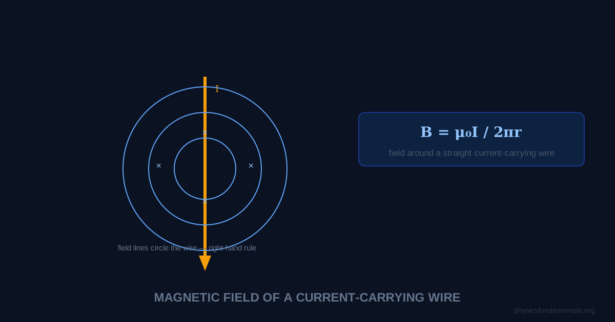
A long straight wire carrying current I produces a magnetic field at distance r from the wire of magnitude B = μ₀I/2πr, where μ₀ = 4π × 10⁻⁷ T·m/A is the permeability of free space. The field forms concentric circular loops around the wire, with direction given by the right-hand rule: wrap the right hand around the wire with the thumb pointing in the current direction — the fingers curl in the direction of the magnetic field.
This result follows from Ampère's law, one of Maxwell's equations, and it connects electric current to the magnetic field it generates — the foundation of electromagnetism. Every electromagnet, motor, generator, and MRI machine exploits this relationship. The force between two parallel current-carrying wires — attractive if currents flow in the same direction, repulsive if opposite — was historically used to define the ampere.
- Magnetic field of a long straight wire: B = μ₀I/2πr
- Right-hand rule for field direction
- Force between two parallel wires: F/L = μ₀I₁I₂/(2πd)
- Solenoid field: B = μ₀nI (n = turns per unit length)
- 4 worked examples including field strength and force calculations
Magnetic Field of a Long Straight Wire
Where:
- B = magnetic flux density (T)
- μ₀ = permeability of free space = 4π × 10⁻⁷ T·m/A ≈ 1.257 × 10⁻⁶ T·m/A
- I = current in the wire (A)
- r = perpendicular distance from the wire (m)
The field decreases as 1/r — halve the distance and the field doubles. This is distinct from a point source (which falls as 1/r²). The circular field lines have no beginning or end — magnetic field lines always form closed loops.
Right-Hand Rule for Wire Field Direction
To find the direction of B around a wire carrying conventional current:
- Point the right thumb in the direction of conventional current flow.
- The fingers curl in the direction of the magnetic field — anticlockwise when viewed from the direction the current is flowing toward you, clockwise when the current flows away.
Using dot/cross notation: if current flows out of the page (•), the field circles anticlockwise. If current flows into the page (×), the field circles clockwise.
Force Between Two Parallel Wires
When two parallel wires carry currents I₁ and I₂ separated by distance d, wire 1's field acts on wire 2's current (and vice versa). The force per unit length between them:
- Same direction currents: attractive force — the wires pull toward each other
- Opposite direction currents: repulsive force — the wires push apart
This formula was historically the definition of the ampere: 1 A is the current in two infinitely long parallel wires separated by 1 m that produces a force of 2 × 10⁻⁷ N per metre of length. (The SI now defines the ampere differently, but the relationship remains.)
Solenoid: B = μ₀nI
A solenoid is a long coil of wire with N turns wound in a tight helix of length L. Inside a long solenoid, the field is uniform and parallel to the axis:
Where n = N/L is the number of turns per unit length (turns/m). Outside a long solenoid, the field is approximately zero — the solenoid concentrates all the field inside it, making it an effective electromagnet.
With a ferromagnetic core (iron): B = μ₀μᵣnI, where μᵣ is the relative permeability of the core (iron: μᵣ ~ 1000–10,000). This enormously amplifies the field, which is why electromagnetic cores are used in motors, transformers, and lifting magnets.
4 Worked Examples
Example 1 — Field strength near a wire
Problem: A long wire carries 8 A. Find the magnetic field strength at distances of: (a) 2 cm, (b) 10 cm from the wire.
Solution:
(a) B = μ₀I/(2πr) = (4π × 10⁻⁷ × 8)/(2π × 0.02) = (3.2π × 10⁻⁶)/(0.04π) = 8 × 10⁻⁵ / 1 = 8.0 × 10⁻⁵ T = 80 μT
(b) B = (4π × 10⁻⁷ × 8)/(2π × 0.10) = 1.6 × 10⁻⁵ T = 16 μT
Increasing distance by 5× reduces B by 5× — confirming the 1/r relationship.
Example 2 — Current from field measurement
Problem: A magnetometer 5 cm from a wire reads 24 μT. Find the current in the wire.
Solution:
B = μ₀I/2πr → I = 2πrB/μ₀ = (2π × 0.05 × 24 × 10⁻⁶)/(4π × 10⁻⁷)
= (π × 0.05 × 24 × 10⁻⁶) × 2 / (4π × 10⁻⁷) = (2.4π × 10⁻⁶)/(4π × 10⁻⁷) = 2.4/0.4 = 6 A
Example 3 — Force between parallel wires
Problem: Two parallel wires are 8 cm apart. Wire 1 carries 5 A, wire 2 carries 3 A, both in the same direction. Find the force per metre between them and state whether it is attractive or repulsive.
Solution:
F/L = μ₀I₁I₂/(2πd) = (4π × 10⁻⁷ × 5 × 3)/(2π × 0.08)
= (60π × 10⁻⁷)/(0.16π) = 60 × 10⁻⁷ / 0.16 = 3.75 × 10⁻⁵ N/m
Same direction currents → attractive
Example 4 — Solenoid field
Problem: A solenoid has 500 turns, length 0.25 m, and carries 2 A. Find the magnetic field inside it.
Solution:
n = N/L = 500/0.25 = 2000 turns/m
B = μ₀nI = 4π × 10⁻⁷ × 2000 × 2 = 4π × 10⁻⁷ × 4000
= 16π × 10⁻⁴ = 5.03 × 10⁻³ T = 5.03 mT
Ampère's Law — The General Principle
The formula B = μ₀I/(2πr) for a long straight wire is a special case of Ampère's law:
The line integral of B around any closed loop equals μ₀ times the total current enclosed. For a circular loop of radius r centred on a long wire: B is constant and parallel to dl everywhere, so B × 2πr = μ₀I → B = μ₀I/(2πr). This is how the formula is derived. Ampère's law is the magnetic analogue of Gauss's law for electric fields, and is one of Maxwell's four equations.
Magnetic Field of a Toroid
A toroid (a solenoid bent into a circle, like a doughnut) confines its magnetic field entirely inside the coil — the field outside is zero. Using Ampère's law for a circular path of radius r inside the toroid with N total turns:
At the central radius r₀: B = μ₀NI/(2πr₀). Toroids are used in switch-mode power supplies, audio transformers, and inductors wherever stray magnetic fields would cause problems — their self-contained fields don't radiate or interfere with nearby components.
Worked Example 5 — Field at the centre of a circular loop
Problem: A circular loop of radius 5 cm carries 3 A. Find the magnetic field at the centre of the loop.
Solution:
For a circular loop (derived from Biot-Savart law, not Ampère's law):
B = μ₀I/(2r) = 4π × 10⁻⁷ × 3/(2 × 0.05) = 12π × 10⁻⁷/0.1 = 120π × 10⁻⁷ = 3.77 × 10⁻⁵ T = 37.7 μT
Direction: right-hand rule — curl fingers in the direction of current flow, thumb points in the direction of B at the centre.
The Biot-Savart Law
For cases without sufficient symmetry to use Ampère's law, the Biot-Savart law gives the field contribution from each element of current:
Where dl is a small current element vector, r̂ is the unit vector from the element to the field point, and r is the distance. Integrating over the complete current path gives the total field. For a long straight wire, integration gives B = μ₀I/(2πr). For a circular loop of radius a, integration along the axis at distance x gives B_axis = μ₀Ia²/(2(a²+x²)^(3/2)) — the on-axis field of a magnetic dipole.
Force on a Current in a Magnetic Field
A current-carrying wire in an external magnetic field experiences a force F = BIL sinθ, where θ is the angle between the wire and B. Direction: right-hand rule or Fleming's left-hand rule (FBI: force = thumb, B field = index finger, current = middle finger). This force is the basis of all electric motors — the turning force (torque) on a current-carrying coil in a permanent magnet field drives the rotation.
For two parallel wires carrying currents I₁ and I₂ separated by distance d:
This force defined the ampere historically: 1 A is the current in two infinite parallel wires 1 m apart that produces 2 × 10⁻⁷ N/m of force. The force is attractive for same-direction currents, repulsive for opposing currents — which is why bus bars (parallel conductors carrying large currents in the same direction) must be mechanically secured against the attractive force pulling them together under fault conditions.
Hall Effect
When a current flows through a conductor in a perpendicular magnetic field, charge carriers are deflected sideways, building up a transverse voltage — the Hall voltage:
Where t is the conductor thickness in the B direction. The Hall effect determines the sign of charge carriers (positive or negative), measures carrier density n, and forms the basis of Hall effect sensors used in smartphones (compass), automotive systems (wheel speed, throttle position), and contactless current measurement. A Hall probe placed in an unknown magnetic field gives V_H = BIt/(nq), from which B is measured with the device pre-calibrated for known n, I, q, t.
Worked Example 6 — Resultant field from two wires
Problem: Two long parallel wires are 10 cm apart. Wire A carries 6 A to the right; Wire B carries 4 A to the left. Find the magnetic field at a point P midway between them.
Solution:
At the midpoint (5 cm from each wire):
B_A = μ₀ × 6/(2π × 0.05) = 4π × 10⁻⁷ × 6/(0.1π) = 24 × 10⁻⁷/0.1 = 2.4 × 10⁻⁵ T
Wire A current goes right → B_A at midpoint points out of the page (right-hand rule: current right, position below wire A → B out of page)
B_B = μ₀ × 4/(2π × 0.05) = 4π × 10⁻⁷ × 4/(0.1π) = 1.6 × 10⁻⁵ T
Wire B current goes left → B_B at midpoint also points out of the page (current left, position above wire B → B out of page)
Both fields point in the same direction, so:
B_total = B_A + B_B = 2.4 × 10⁻⁵ + 1.6 × 10⁻⁵ = 4.0 × 10⁻⁵ T out of the page
MRI Scanners — Strong Uniform Magnetic Fields
MRI (Magnetic Resonance Imaging) scanners use solenoids wound with superconducting wire to produce highly uniform magnetic fields of 1.5–7 T over a volume large enough to contain a human. The field uniformity within the imaging volume must be better than 1 part per million — a 1.5 T field varying by more than 1.5 μT across the patient would distort the images. This requires precisely wound solenoid coils, supplementary correction coils (shimming), and complete shielding from external ferromagnetic objects. The fringe field outside the scanner can be 5 mT or more at 5 metres — enough to attract surgical instruments, wheelchairs, and oxygen cylinders with lethal force, which is why MRI rooms have strict exclusion zones.
Exam Summary
Key formulas: B = μ₀I/(2πr) for a long wire (field decreases as 1/r); B = μ₀nI for a solenoid (n = N/L, uniform inside, zero outside); F/L = μ₀I₁I₂/(2πd) for the force between two parallel wires; F = BIL sinθ for force on a current-carrying wire in a field. Direction always from right-hand rule: thumb in current direction, fingers curl in the direction of circular field lines around a wire; for force on a current in a field, use Fleming's left-hand rule (FBI). The μ₀ = 4π × 10⁻⁷ T·m/A should be memorised or looked up — it appears in every magnetic field formula.
Magnetic fields from current-carrying wires are central to modern technology. Every electric motor, every generator, every transformer, every inductor exploits the field created by current in a conductor. The solenoid — current through a helical coil — is the canonical electromagnet, and every electromagnetic relay, MRI machine, and particle accelerator magnet is essentially a refined solenoid. The 1/r field of a long wire and the uniform field of a solenoid (B = μ₀nI) are the two most important field geometries in practical electromagnetics, and their derivation from Ampère's law and Biot-Savart are the cornerstones of electromagnetic field theory.
The connection between electricity and magnetism — a current creates a magnetic field — was discovered accidentally by Hans Christian Ørsted in 1820 when he noticed a compass needle deflecting near a current-carrying wire during a lecture demonstration. This observation launched the field of electromagnetism, driving Ampère, Faraday, and ultimately Maxwell to unify electricity and magnetism into a single framework. The formula B = μ₀I/(2πr) is the quantitative expression of Ørsted's discovery: any wire carrying current is surrounded by a magnetic field whose strength falls off with distance and is proportional to the current. From this one relationship, via Faraday's and Maxwell's extensions, the entire theory of electromagnetism — and consequently all of modern electronics, power generation, and communications — eventually followed.
Frequently Asked Questions
What is the magnetic field formula for a current-carrying wire?
Why do parallel wires with currents in the same direction attract?
What is a solenoid and what field does it produce?
How does the magnetic field of a wire differ from that of a bar magnet?
What is permeability of free space μ₀?
Share this article
Written by
Physics Fundamentals Editorial Team
Written and reviewed by our team of physics educators. Content is aligned with A-Level, GCSE, AP Physics, and undergraduate curricula.
About Physics Fundamentals →