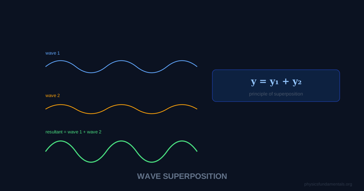
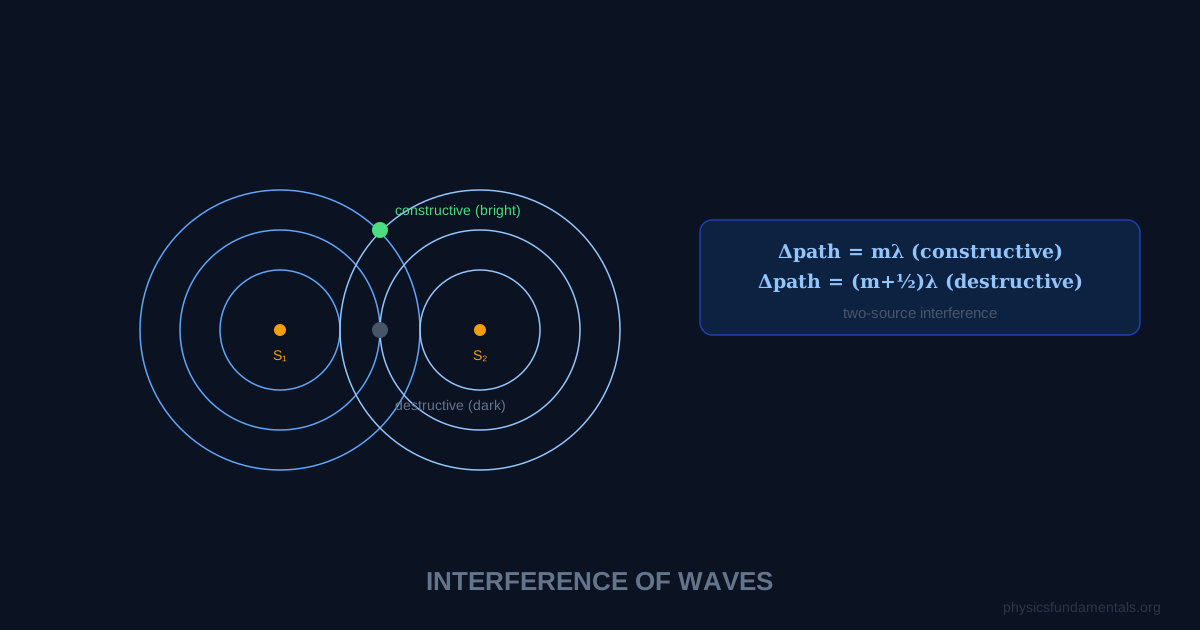
Wave interference occurs when two or more waves overlap in space — the displacement at each point is the sum of all individual wave displacements (the superposition principle). Constructive interference occurs where waves add together (path difference = nλ, where n = 0, 1, 2...), producing a larger amplitude. Destructive interference occurs where they cancel (path difference = (n+½)λ), producing zero or reduced amplitude. This is why Young's double slit produces a pattern of bright and dark fringes.
Interference is one of the defining proofs of the wave nature of light. Particles don't interfere — they simply pile up. But waves do. When Thomas Young demonstrated interference of light in 1801, he conclusively showed that light was a wave, settling a century-long debate with Newton over whether light was corpuscular or wave-like.
- The superposition principle — how to add waves algebraically
- Constructive interference: path difference = nλ, phase difference = 0, 2π, 4π...
- Destructive interference: path difference = (n+½)λ, phase difference = π, 3π...
- Coherence — why sources must be coherent to produce stable interference
- 4 worked examples including path difference and fringe calculations
The Superposition Principle
When two or more waves overlap, the resultant displacement at any point is the algebraic sum of the individual displacements at that point.
The superposition principle applies to all linear waves: water waves, sound waves, light waves, microwaves, string waves. It fails only for very high amplitude waves where the medium behaves nonlinearly.
Constructive Interference
Constructive interference occurs when two waves arrive at a point in phase — crest meets crest, trough meets trough.
Result: amplitude doubles (for identical amplitude waves), intensity quadruples.
Destructive Interference
Destructive interference occurs when waves arrive exactly out of phase — crest meets trough.
Result: zero amplitude (complete cancellation) for identical amplitude waves.
Path Difference and Phase Difference
The relationship between path difference (Δx) and phase difference (Δφ):
A path difference of one wavelength corresponds to a phase difference of 2π (one full cycle) — constructive. Half a wavelength gives π — destructive.
Coherence
For stable interference patterns, wave sources must be coherent: same frequency and a constant (not random) phase relationship. Two separate light bulbs are not coherent — their random phase fluctuations average out any interference pattern. Laser light is coherent; a laser beam split into two paths and recombined produces stable interference.
In Young's double slit, a single light source illuminates both slits — making them coherent secondary sources derived from the same wavefront.
4 Worked Examples
Example 1 — Constructive or destructive?
Problem: Two speakers emit sound of wavelength 0.4 m. Point P is 2.4 m from speaker 1 and 3.0 m from speaker 2. Is the interference constructive or destructive at P?
Solution:
Path difference = 3.0 − 2.4 = 0.6 m
0.6/0.4 = 1.5 = 3/2 → path difference = 1.5λ = (n+½)λ with n=1
Destructive interference — point P is a minimum.
Example 2 — Finding wavelength from interference
Problem: In a microwave experiment, a detector finds maxima at 0, 3 cm, 6 cm, 9 cm from the centre. What is the microwave wavelength?
Solution:
Maxima occur at path differences of nλ. Adjacent maxima differ by λ = 3 cm.
Example 3 — Phase difference from path difference
Problem: Light of wavelength 600 nm has a path difference of 900 nm at a point. Find the phase difference and state the type of interference.
Solution:
Δφ = (2π/λ) × Δx = (2π/600) × 900 = 3π radians
3π = odd multiple of π → destructive interference
Example 4 — Double slit fringe spacing
Problem: Light of wavelength 550 nm passes through two slits 0.5 mm apart, and fringes are observed on a screen 2 m away. Find the fringe spacing.
Solution:
Fringe spacing = λD/d = (550 × 10⁻⁹ × 2)/(0.5 × 10⁻³) = 1100 × 10⁻⁹ / 5 × 10⁻⁴ = 2.2 × 10⁻³ m = 2.2 mm
Interference in Everyday Life
Noise-cancelling headphones use destructive interference — a microphone picks up ambient noise, electronics invert the signal (shifting phase by π), and the inverted wave cancels the original noise.
Thin film colours (soap bubbles, oil films, butterfly wings) arise from interference between light reflecting from the top and bottom surfaces of a thin film. Different wavelengths interfere constructively or destructively at different thicknesses, producing vivid colours.
Anti-reflection coatings on camera lenses use a thin coating chosen to create destructive interference for reflected light, reducing glare and increasing transmission.
Young's Double-Slit Experiment — The Numbers
Young's 1801 experiment used sunlight through two narrow slits separated by distance d. Bright fringes appear where path difference = nλ; dark fringes where path difference = (n+½)λ. The fringe spacing w (distance between adjacent bright or dark fringes) on a screen at distance D:
For typical values (d = 0.5 mm, D = 2 m, λ = 589 nm): w = 589 × 10⁻⁹ × 2/0.5 × 10⁻³ = 2.36 mm. The fringes are millimetre-scale — visible to the naked eye. This is how Young measured the wavelength of light in 1801 — rearranging w = λD/d → λ = wd/D. His value (∼570 nm) was close to the modern value for yellow light, confirming the wave nature of light at a time when Newton's particle ("corpuscular") theory was dominant.
Coherence — Why Two Separate Sources Don't Interfere
Interference fringes only appear when the two sources are coherent — same frequency and a constant phase relationship. Two separate light bulbs do not produce interference fringes because:
- Different phases: atoms in each bulb emit independently. The phase difference between the two sources changes randomly every ~10⁻⁸ seconds — far too fast to observe stationary fringes.
- Multiple wavelengths: white light contains all visible wavelengths. Different wavelengths produce fringe patterns of different spacings that overlap and wash out.
Solutions: (1) derive both beams from the same source (Young's method — both slits illuminated by the same point source); (2) use a laser (coherent, monochromatic). Two separate lasers of the same frequency can sometimes interfere if phase-locked, but in general, derive both beams from the same laser for reliable fringes.
Interference in Thin Films
The iridescent colours of soap bubbles, oil films on puddles, and beetle wing cases arise from thin film interference. Light reflects from the top and bottom surfaces of the thin film. The path difference between the two reflected beams depends on the film thickness t and the refractive index n:
Constructive interference (bright for that wavelength) when 2nt = (m+½)λ for one surface causing a phase flip (common case). Destructive interference (dark) when 2nt = mλ. Different thicknesses in a soap bubble produce different colours — the swirling colour pattern maps the varying thickness of the film.
Anti-reflection coatings on camera lenses and spectacles use destructive thin film interference to eliminate reflections. A quarter-wavelength thick coating (2nt = λ/2) produces a path difference of λ/2, exactly cancelling the reflected wave. Modern multi-layer coatings stack several such films tuned to different wavelengths, achieving reflectivity below 0.1% across the visible spectrum.
Worked Example 5 — Thin film calculation
Problem: A thin film of oil (n = 1.45) floats on water. White light illuminates the film from above. For what minimum film thickness does the film appear green (λ = 520 nm in vacuum) in reflection?
Solution:
Light reflects from air-to-oil (phase flip, n increases) and oil-to-water (phase flip if n_water > n_oil; water n = 1.33 < 1.45 so NO phase flip at oil-water surface).
Net phase difference from reflections: one flip only → destructive when 2nt = mλ; constructive when 2nt = (m+½)λ.
For minimum thickness (m=0): 2nt = λ/2 → t = λ/(4n) = 520/(4 × 1.45) = 520/5.8 = 89.7 nm
Interference in Sound — Noise-Cancelling Headphones
Noise-cancelling headphones use active destructive interference. A microphone on the earcup samples incoming noise; electronics generate a signal with the same amplitude but opposite phase (shifted by 180°); the speaker plays this anti-phase signal into the ear. The destructive interference cancels the noise. The system works best for low-frequency steady noise (engine rumble, aircraft cabin noise) where electronics can process the signal fast enough. High-frequency or rapidly changing sounds are harder to cancel — the electronics can't keep up. Passive noise isolation (thick earpads) handles high frequencies better, which is why premium headphones combine both approaches.
Michelson Interferometer
The Michelson interferometer splits a beam into two perpendicular paths, reflects each off a mirror, and recombines them. The path difference between the two arms determines whether constructive or destructive interference occurs. Moving one mirror by λ/2 shifts the path difference by λ, switching from bright to dark and back. This allows mirror displacement to be measured with sub-nanometre precision. The Michelson interferometer was famously used in the 1887 Michelson-Morley experiment that found no evidence for the luminiferous ether — a null result that contributed to Einstein's development of special relativity. LIGO gravitational wave detectors are kilometre-scale Michelson interferometers, measuring mirror displacements of 10⁻¹⁹ m — one-thousandth the diameter of a proton.
Worked Example 6 — Young's double slit calculation
Problem: In a double-slit experiment, the slit separation is 0.4 mm and the screen is 1.8 m from the slits. The fringe spacing is measured as 2.7 mm. Find the wavelength of the light used.
Solution:
w = λD/d → λ = wd/D = 2.7 × 10⁻³ × 0.4 × 10⁻³/1.8 = 1.08 × 10⁻⁶/1.8 = 6.0 × 10⁻⁷ m = 600 nm (orange-red light)
Exam Summary for Interference
Two conditions for observable interference: (1) the sources must be coherent (same frequency, constant phase difference); (2) the amplitudes must be comparable (if one source is much stronger, contrast is poor). Key formula: fringe spacing w = λD/d (valid when d ≪ D, i.e. small angle approximation sinθ ≈ tanθ ≈ θ applies). Constructive interference at path difference nλ; destructive at (n+½)λ. In thin film problems, count phase flips at each reflection (flip when going from lower to higher refractive index) before determining whether the path difference gives constructive or destructive interference. Coherence is the key conceptual point that distinguishes interference from random superposition: without coherence, no stable fringe pattern forms.
Applications of Interference in Technology
Interference is exploited across modern technology. Optical coatings on telescope mirrors use constructive interference to maximise reflectivity at specific wavelengths. Holography records the full interference pattern between a reference beam and the object beam — reconstruction recreates a three-dimensional image by replaying the same wave pattern. Spectral filters use multiple thin film layers to transmit only specific wavelengths, used in laser systems, astronomy, and fluorescence microscopy. Optical fibre sensors use interferometry to measure strain, temperature, and pressure with sub-micrometre precision — embedded in bridges, aircraft wings, and oil pipelines for structural health monitoring. Every one of these technologies would be impossible without the precise, predictable behaviour of constructive and destructive interference that Young first demonstrated with two slits and a candle in 1801.
Radio Wave Interference and Dead Zones
Two radio transmitters broadcasting on the same frequency can create interference patterns in the surrounding area. Where signals arrive in phase (path difference = nλ), reception is strong. Where they arrive out of phase (path difference = (n+½)λ), destructive interference creates "dead zones" where reception is poor. This is a practical problem for AM radio stations — the original reason FM radio was developed (FM is much less susceptible to multipath interference). In mobile communications, multiple signals arriving at a phone via different reflective paths (multipath propagation) can interfere destructively at specific locations, causing signal dropouts — a problem solved by antenna diversity (multiple antennas at different positions) and OFDM modulation techniques used in 4G and 5G.
Worked Example 7 — Calculating wavelength from fringe data
Problem: In a Young's double-slit experiment with slit separation 1.2 mm and screen distance 3.0 m, the distance between the 1st and 5th bright fringes is 8.0 mm. Find the wavelength of the light.
Solution:
Distance between 1st and 5th fringe = 4 fringe spacings = 4w
w = 8.0/4 = 2.0 mm = 2.0 × 10⁻³ m
λ = wd/D = 2.0 × 10⁻³ × 1.2 × 10⁻³/3.0 = 2.4 × 10⁻⁶/3.0 = 8.0 × 10⁻⁷ m = 800 nm (near infrared)
Note: measuring between the nth and (n+4)th fringe, not between fringes 1 and 5 counting from zero, which would give 5w. Always count the number of gaps, not the number of fringes. This is a classic exam trap — the distance from fringe 1 to fringe 5 spans 4 inter-fringe spacings.
Interference is fundamentally about phase relationships. Two waves that start in phase and travel different distances accumulate a phase difference φ = 2π × (path difference)/λ. When φ = 2nπ (path difference = nλ): constructive, amplitudes add. When φ = (2n+1)π (path difference = (n+½)λ): destructive, amplitudes cancel. The intensity at any point I ∝ cos²(φ/2) — maximum at φ = 0, 2π, 4π; zero at φ = π, 3π, 5π. The entire field of wave optics — diffraction gratings, thin films, interferometry, holography — is the study of these phase relationships at different geometrical configurations. Mastering the path difference ↔ phase difference ↔ constructive/destructive relationship is the key to all wave optics problems.
The key difference between interference and diffraction is often confused. Interference is the superposition of waves from discrete separate sources (two slits, two loudspeakers). Diffraction is the bending and spreading of a wave as it passes through an aperture or around an obstacle — it occurs with a single opening. In practice, both occur together in any real experiment: light diffracts through each individual slit and then the diffracted beams from different slits interfere. The observed pattern combines both effects: the fringe positions are set by the slit separation (interference), while the envelope of intensities is set by the individual slit width (diffraction). Understanding both together is essential for correctly interpreting any multi-slit or grating experiment.
Try it yourself: check your own numbers with the Double-Slit Fringe Spacing Calculator, which shows the formula, the worked substitution and the answer step by step.
Frequently Asked Questions
What is wave interference?
What is the condition for constructive interference?
What is destructive interference?
Does destructive interference violate conservation of energy?
What is coherence and why is it needed for interference?
Share this article
Written by
Physics Fundamentals Editorial Team
Written and reviewed by our team of physics educators. Content is aligned with A-Level, GCSE, AP Physics, and undergraduate curricula.
About Physics Fundamentals →