A capacitor stores electric charge — and the capacitance C = Q/V tells you how much charge (Q, in coulombs) a capacitor stores per volt of potential difference (V). Capacitance is measured in farads (F), where 1 F = 1 C/V. In practice, most capacitors are in the microfarad (μF, 10⁻⁶ F) to picofarad (pF, 10⁻¹² F) range — a 1-farad capacitor is enormous by electronics standards.
Capacitors are everywhere in electronics: camera flashes, power supplies, radio tuners, defibrillators, touchscreens, and RAM in computers all use capacitors. The reason is that they store energy in an electric field and can release it almost instantly — unlike a battery, which releases energy through a relatively slow chemical reaction.
- The capacitance formula C = Q/V and what a farad actually represents
- Energy stored in a capacitor: E = ½CV² = ½QV = Q²/2C
- Capacitors in series and parallel — the rules (opposite to resistors)
- Charging and discharging: the exponential decay Q = Q₀e^(−t/RC)
- The parallel plate capacitor: C = ε₀A/d
What Is a Capacitor?
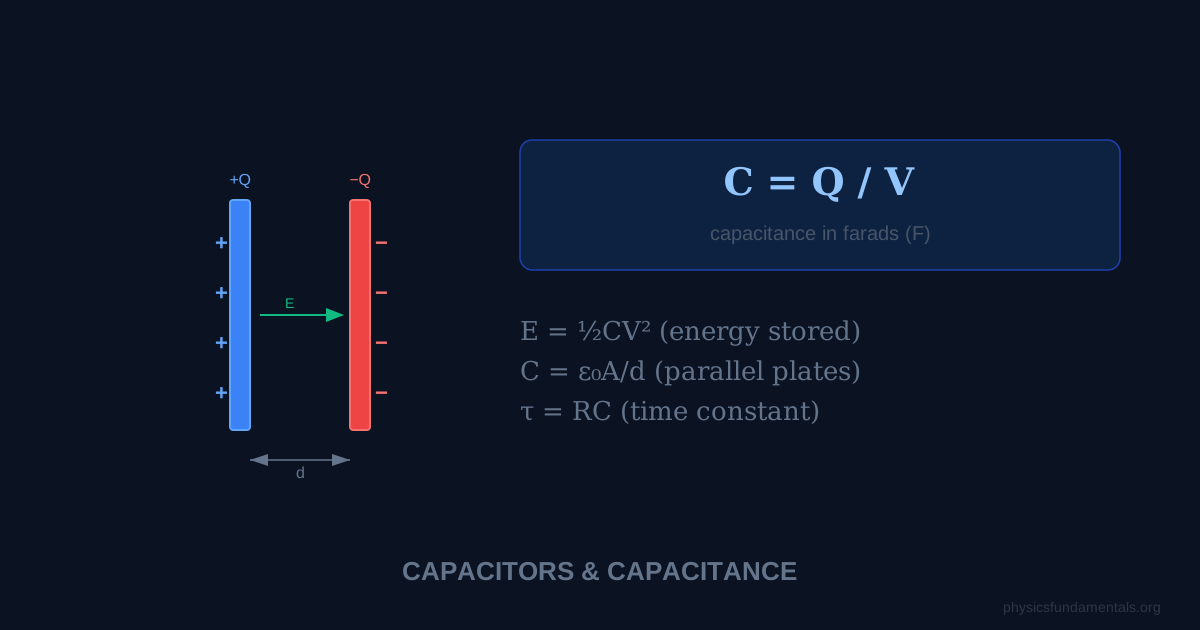
A capacitor is an electrical component that stores energy in an electric field. In its simplest form, it consists of two conducting plates separated by an insulating material (the dielectric). When connected to a voltage source, equal and opposite charges accumulate on the plates, creating an electric field between them.
The key thing a capacitor does is separate charge: one plate accumulates positive charge (+Q) while the other accumulates negative charge (−Q). The electric field between the plates stores the energy. When the capacitor is disconnected and connected to a circuit, it releases this stored energy by driving current.
Capacitance: C = Q/V
Where:
- C = capacitance, in farads (F)
- Q = charge stored on one plate, in coulombs (C)
- V = potential difference across the capacitor, in volts (V)
Rearrangements: Q = CV and V = Q/C.
Capacitance is a property of the capacitor itself — it depends on the geometry and materials, not on how much charge has been placed on it. A capacitor with C = 100 μF stores 100 μC of charge for every 1 V across it, 500 μC for 5 V, and so on — a perfectly linear relationship.
The parallel plate capacitor
For two parallel conducting plates of area A separated by distance d, with a vacuum (or air) between them:
Where ε₀ = 8.854 × 10⁻¹² F/m is the permittivity of free space. With a dielectric material of relative permittivity ε_r between the plates:
This shows that capacitance increases with: larger plate area A (more space to store charge), smaller separation d (stronger electric field per unit charge, higher capacitance), and higher permittivity material between the plates.
Energy Stored in a Capacitor
The energy stored in a charged capacitor is:
All three forms are equivalent (use C = Q/V to convert between them). The most commonly used is E = ½CV².
Where does the ½ come from? When you start charging a capacitor, the first bit of charge arrives with no opposing voltage — it's easy. As charge builds up, the voltage increases, and each subsequent unit of charge has to be pushed against a growing voltage. The average voltage during charging is V/2, giving E = Q × (V/2) = ½QV = ½CV².
Capacitors in Series and Parallel
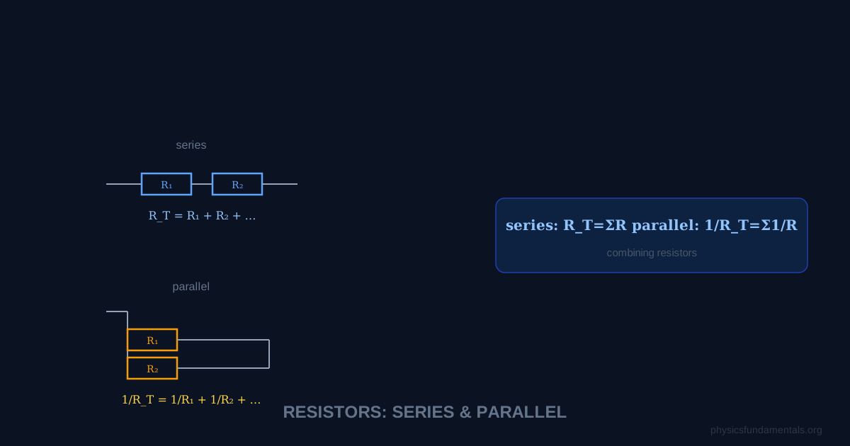
The combination rules for capacitors are the opposite of resistors — a common exam trap.
Capacitors in parallel
In parallel, capacitors share the same voltage. Their charge-storing abilities simply add. Total capacitance is always greater than the largest individual capacitor.
Capacitors in series
In series, the same charge appears on each capacitor (charge from one plate of C₁ migrates to charge C₂, and so on). Total capacitance is always less than the smallest individual capacitor.
For two capacitors in series:
Resistors in series add directly (R = R₁ + R₂). Capacitors in parallel add directly (C = C₁ + C₂).
Resistors in parallel use reciprocals. Capacitors in series use reciprocals.
They're exactly swapped.
4 Worked Examples
Example 1 — Charge and voltage
Problem: A 47 μF capacitor is connected to a 12 V supply. Find: (a) the charge stored, (b) the energy stored.
Solution:
(a) Q = CV = 47 × 10⁻⁶ × 12 = 5.64 × 10⁻⁴ C = 564 μC
(b) E = ½CV² = ½ × 47 × 10⁻⁶ × 12² = ½ × 47 × 10⁻⁶ × 144 = 3.38 × 10⁻³ J = 3.38 mJ
Example 2 — Capacitors in parallel
Problem: Three capacitors of 10 μF, 22 μF, and 33 μF are connected in parallel across a 5 V supply. Find the total capacitance and total charge stored.
Solution:
C_total = 10 + 22 + 33 = 65 μF
Q_total = C_total × V = 65 × 10⁻⁶ × 5 = 325 μC
Example 3 — Capacitors in series
Problem: A 6 μF and a 12 μF capacitor are connected in series across 9 V. Find: (a) total capacitance, (b) charge on each capacitor, (c) voltage across each.
Solution:
(a) C_total = (6 × 12)/(6 + 12) = 72/18 = 4 μF
(b) In series, Q is the same on both: Q = C_total × V = 4 × 10⁻⁶ × 9 = 36 μC
(c) V₁ = Q/C₁ = 36 × 10⁻⁶ / 6 × 10⁻⁶ = 6 V; V₂ = 36 × 10⁻⁶ / 12 × 10⁻⁶ = 3 V
Check: 6 + 3 = 9 V ✓
Example 4 — Energy in a camera flash
Problem: A camera flash uses a 1000 μF capacitor charged to 300 V. How much energy is released per flash?
Solution:
E = ½CV² = ½ × 1000 × 10⁻⁶ × 300²
E = ½ × 10⁻³ × 90,000
E = 45 J
45 joules released in a fraction of a second — that's the instantaneous power delivery that makes a flash so bright. A battery could store this energy too, but couldn't release it fast enough.
Charging and Discharging: The RC Time Constant
When a capacitor charges or discharges through a resistor R, the charge follows an exponential curve:
Charging (from 0 to full charge Q₀ = CV):
Discharging (from Q₀ to 0):
The time constant τ = RC is the time for the charge to fall to 1/e ≈ 37% of its initial value during discharging (or to reach 63% during charging).
- After 1τ: 63% charged (or 37% remaining when discharging)
- After 2τ: 86% charged (14% remaining)
- After 5τ: 99.3% — considered "fully charged" in practice
A 100 μF capacitor discharging through a 10 kΩ resistor has τ = RC = 10,000 × 100 × 10⁻⁶ = 1 second. After 5 seconds, it's essentially fully discharged.
Real-World Applications
Power supply smoothing: Rectifiers convert AC to DC but produce pulsating DC. Large capacitors in parallel with the load charge up on peaks and discharge between them, smoothing the ripple into steady DC.
Camera flash: A capacitor charges slowly from a battery over a few seconds, then discharges in milliseconds through a flash tube — delivering far more instantaneous power than the battery could directly.
Defibrillators: Medical defibrillators charge capacitors to 2,000–5,000 V and discharge through the patient's chest to restart the heart — delivering several hundred joules in milliseconds.
Touchscreens: Capacitive touchscreens detect fingers by measuring changes in capacitance at each point of a grid. A finger changes the local electric field, altering the capacitance — the processor maps these changes to a touch location.
Capacitors in AC Circuits — Capacitive Reactance
In a DC circuit, a capacitor fully charged to the supply voltage allows no steady current. In an AC circuit, the capacitor repeatedly charges and discharges as the voltage alternates, creating an effective opposition to current flow called capacitive reactance X_C:
Where f is the AC frequency (Hz) and C is capacitance (F). X_C decreases with increasing frequency — at high frequencies, the capacitor charges and discharges so rapidly that it barely opposes the current. At low frequencies, the period is long, the capacitor builds up charge, and it blocks current more effectively. At DC (f = 0), X_C → ∞ and no steady current flows. This frequency-dependent behaviour makes capacitors essential components in filters, signal processing, and tuned circuits.
Dielectrics and Their Effect on Capacitance
Inserting a dielectric (insulating material) between capacitor plates increases capacitance by the relative permittivity ε_r of the material:
Why does this happen? A dielectric is a polarisable material — its molecules develop electric dipoles in the applied field. These dipoles produce their own field opposing the applied field, reducing the voltage across the capacitor for the same stored charge. Since C = Q/V, lower V for the same Q means higher C. This is equivalent to saying the dielectric partially cancels the electric field between the plates, allowing more charge to be stored before the voltage limit is reached.
| Material | Relative permittivity ε_r | Breakdown voltage (MV/m) |
|---|---|---|
| Air (vacuum) | 1.0 | 3 |
| Paper | 3.5 | 16 |
| Polypropylene | 2.2 | 650 |
| Ceramic (BaTiO₃) | ~1000–10,000 | ~3 |
| Water | 80 | ~65 |
Worked Example 5 — Capacitor design
Problem: Design a parallel plate capacitor with C = 100 nF using polypropylene dielectric (ε_r = 2.2, thickness d = 20 μm). Find the plate area required.
Solution:
C = ε₀ε_r A/d → A = Cd/(ε₀ε_r)
A = (100 × 10⁻⁹ × 20 × 10⁻⁶)/(8.854 × 10⁻¹² × 2.2)
A = (2 × 10⁻¹²)/(1.948 × 10⁻¹¹) = 0.1027 m² ≈ 1027 cm²
This is about 32 cm × 32 cm — hence why real capacitors use thin dielectric films rolled into compact cylinders.
Capacitor Safety — Stored Energy Hazards
Large capacitors can be extremely dangerous even when disconnected from power. The energy stored E = ½CV² can be released in milliseconds — far too fast for a circuit breaker to respond. A 1000 μF capacitor charged to 400 V stores ½ × 10⁻³ × 160,000 = 80 J and can deliver this in milliseconds, equivalent to a peak current of thousands of amperes. This is comparable to a defibrillator shock. Large capacitor banks in industrial equipment and in CRT televisions remain charged for hours or days after power is removed — always discharge capacitors through a resistor before working on high-voltage circuits.
Exponential Charging and Discharging in Detail
During capacitor charging through resistance R:
During discharge:
The initial discharge current I₀ = V₀/R can be very large if R is small — another reason large charged capacitors are dangerous. A practical rule: use a series resistor of at least 1 kΩ when deliberately discharging a capacitor to limit peak current.
Capacitors vs Batteries: Complementary Energy Storage
Capacitors and batteries are both energy storage devices but serve very different roles. A battery stores 100–300 Wh/kg and delivers it over hours at near-constant voltage. A capacitor stores ~0.01–0.1 Wh/kg but can deliver it in milliseconds with very high peak power — 10,000 W/kg or more. Supercapacitors (electric double-layer capacitors) bridge the gap with ~5 Wh/kg and ~10,000 W/kg, used in hybrid buses for regenerative braking energy capture and fast release during acceleration. The fundamental trade-off — energy density vs power density — makes capacitors and batteries complementary rather than competing technologies.
Common Exam Mistakes with Capacitors
Mistake 1 — Getting series/parallel rules backwards. Capacitors in parallel add directly (like resistors in series). Capacitors in series use the reciprocal rule (like resistors in parallel). The rule swap confuses many students. Memory aid: capacitors in parallel share the same voltage — more voltage exposed to more plate area, so capacitance adds. In series, the same charge appears on each — the plates effectively get further apart, reducing total capacitance.
Mistake 2 — Forgetting the ½ in energy formulas. E = ½CV² not CV². The ½ comes from the fact that the voltage builds up from 0 to V during charging, so the average voltage during the charging process is V/2. A capacitor storing charge Q at voltage V has energy ½QV, not QV.
Mistake 3 — Confusing charge and voltage after connecting capacitors. When two charged capacitors are connected in parallel, charge redistributes until they reach the same voltage. The total charge is conserved (Q_total = Q₁ + Q₂) and the final voltage is V_final = Q_total/(C₁ + C₂). Energy is not conserved in this process — some is lost as heat in the connecting wire resistance.
Exam questions frequently combine capacitor circuits with energy calculations. Always identify whether capacitors are in series or parallel first — this determines both total capacitance and whether charge or voltage is shared. For series: same Q on each, voltages add to give supply voltage. For parallel: same V across each, charges add to give total stored charge. The maximum working voltage of a capacitor is always the voltage of the capacitor with the smallest rating — in a series chain, the one with lowest capacitance receives the highest voltage.
Try it yourself: check your own numbers with the Capacitor Charge & Energy Calculator, which shows the formula, the worked substitution and the answer step by step.
Frequently Asked Questions
What is capacitance?
What is the energy stored in a capacitor?
How are capacitors different in series vs parallel?
What is the RC time constant?
What is the difference between a capacitor and a battery?
Share this article
Written by
Physics Fundamentals Editorial Team
Written and reviewed by our team of physics educators. Content is aligned with A-Level, GCSE, AP Physics, and undergraduate curricula.
About Physics Fundamentals →